Distributed Control System (DCS) Explained

A Distributed Control System (DCS) is a type of automated industrial control system (ICS) used to control geographically distributed processes, such as those in factories, power plants, and other large industrial settings. DCS systems rely on a network of controllers distributed across a facility, allowing for real-time monitoring and control of multiple processes simultaneously. These systems are integral in industries where precise, continuous control is essential. Read on to learn more about the meaning of DCS.

What is a DCS?

A Distributed Control System (DCS) is a computerized control system that streamlines the functionalities of industrial devices used throughout a workspace. A DCS utilizes a wide range of controllers to permit all the parts to converse with one another just as PCs do. These controllers are distributed geographically across a plant to allow for high-speed communication to the control process. When utilizing various kinds of modules, the framework may require diverse correspondence norms, for example, Modbus and Profibus.
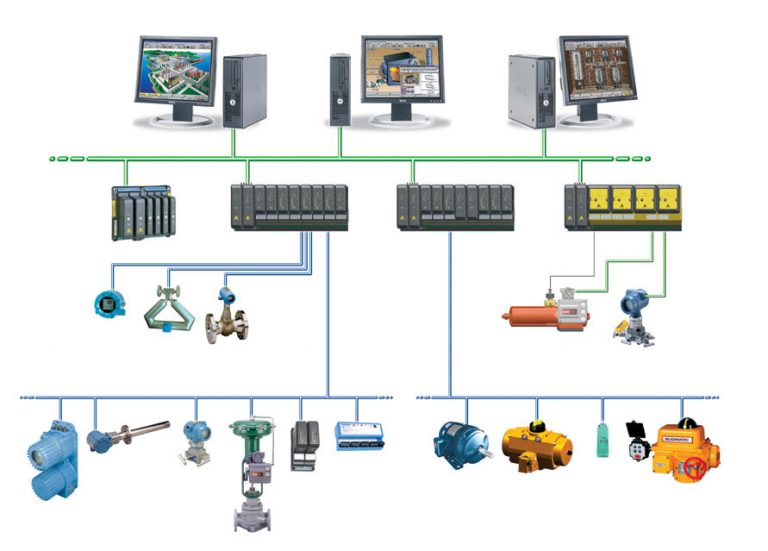
What is a Distributed Control System
Distributed Control System Layout
Read More
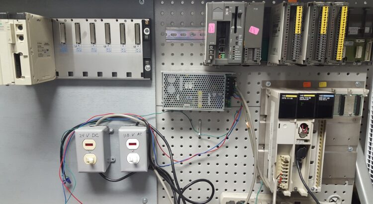
A PLC installed alongside other components

What Is a PLC (Programmable Logic Controller)?

What Does “PLC” Stand For?

A Programmable Logic Controller, abbreviated as “PLC” is a computer used to address the issues of a particular assembling process. These devices come in a wide range of shapes and sizes, with numerous alternatives for computerized and simple I/O, as well as protection from high temperatures, vibration, and electrical noise. The invention of the PLC allows for computers to be streamlined into the industrial automation process.

A PLC can be a solitary device figuring and executing operations, or a rack of various modules utilized to meet whatever your automation system requires. A portion of the extra parts include processors, power supplies, additional IO, interfaces, and more. Each part cooperates to have the option to run open or shut circle activities that are appraised at fast and high accuracy. Take a CNC machine for instance; a PLC would be utilized to control positioning, motion, and torque control. These devices are popular since they are inexpensive in relation to the amount of power and lifespan they possess. PLCs can run for hours on end. 

Read More

UD75 Configuration and Setup

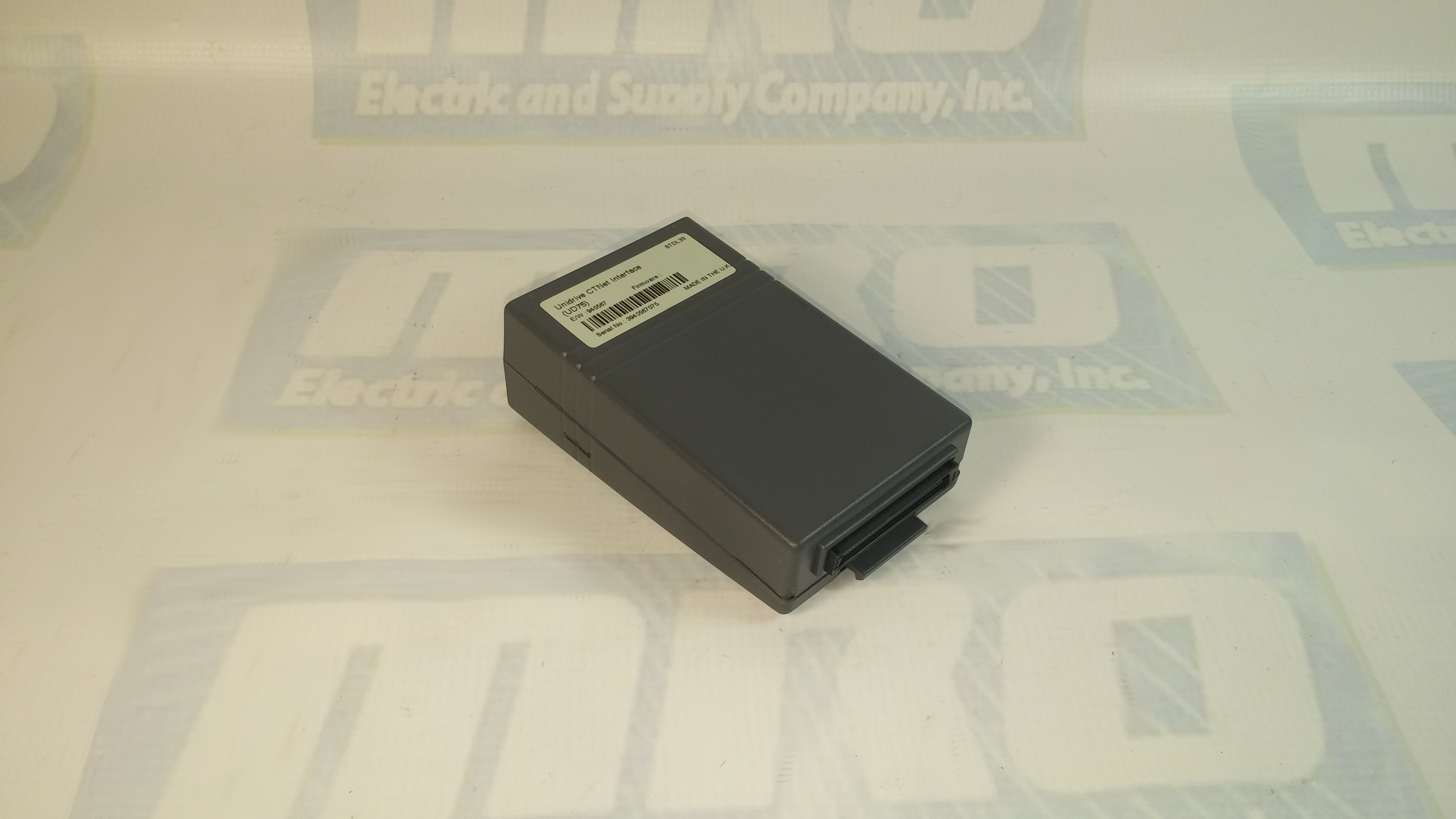
You can check out our previous blog post  on the UD75 here for more information. Check out the UD75 product page on our website along with all of our other Unidrive options.

UD75 Configuration
  1. Isolate the drive from the mains supply and allow 5 minutes for the DC Bus capacitors to discharge.
  2. Insert Large Option Module as shown below. Ensure that it is correctly inserted. The module will click firmly into place.
  3. To remove the module, pull on the black tab, and the module will disengage from the connector and pull out of the drive.
UD75 Configuration: Cable Screen
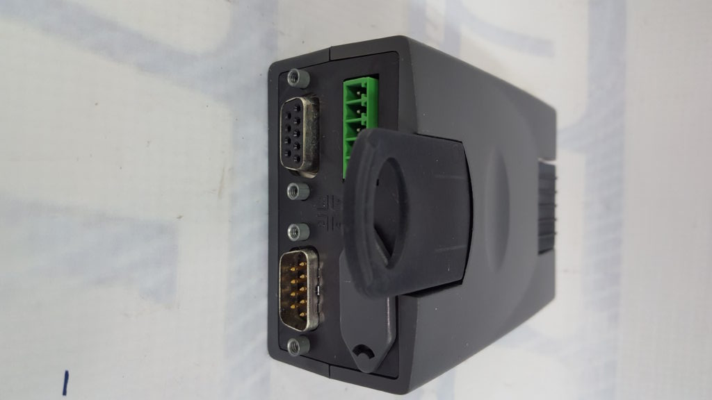
The screen of the cable at every node on the network MUST be connected to the screen terminal (pin 3) on the CTNet terminal block. When the screen is stripped back to connect the twisted pair to the CTNet terminals, keep the exposed section of the cable as short as possible. On the CTNet PC Interface Adapter Card, there is no screen terminal. The screen should be cut and taped back to prevent it coming into contact with any other surfaces. The on-board terminal resistor should not be connected.
UD75 Configuration: Network Termination
The network MUST be fitted with terminating resistors AT BOTH ENDS!!! If resistors are not fitted, the network appear to work OK, but the noise immunity of the network will be drastically reduced. The terminating resistor value should match the nominal characteristic impedance value for the cable; in the case of the customized CTNet cable, the terminating resistors used should be nominally 78Ω. PC ISA and PCMCIA cards for interfacing a PC to CTNet are available from CT SSPD.

For price and ordering info you can email sales@mroelectric.com or call 1-800-691-8511. We have these and all the other Control Techniques Unidrive Classic option modules in stock, along with the drives themselves.

UD75 Configuration
UD75 Configuration

UD73 Configuration and Setup

You can check out our previous blog post on the UD73 here for additional setup and configuration info.

For UD73 configuration, most common parameters are arranged in one concise menu. Hundreds of user-configurable functions separated into 20 logical menus provide quick setup for advanced application. For positioning, ratio control, camming and multi-axis systems, plug-in option modules easily extend the Unidrive’s capabilities. High horsepower Unidrives cover the range from 200 to 1600 HP. The 300 amp power module and control pod (the “brain”) are available as components. They are also available as a packaged drive solution that includes fusing and a disconnect. (See our Packaged Drive Section, pages 120-123 and 128-133.) With the UD73’s extensive selection of communication, application, feedback and I/O modules, you can easily upgrade the performance of your drive. Yet, it is simple to configure by using the drive keypad, a remote keypad (CTKP), or UniSoft, the UD73 Windows based drive set-up tool. You can tailor each Unidrive to be the drive you want when you want it.
    • Digital AC Drive
    • 1 to 30 HP, 3 Phase, 208-230 VAC
    • 1 to 1600 HP, 3 Phase, 380-460 VAC
    • Five operating modes
        • V/Hz
        • Open loop vector
        • Closed loop vector
        • Brushless AC servo
      • Regenerative
    • UniSoft Windows based configuration tool
    • Configurable analog and digital I/O
  • Complete Motor Solutions
The UD73 configuration is suited for use with AC brushless servo motors. Servo control is ideal for applications requiring load transfer to and from any position, at any speed. The UD73 is designed for both stand-alone and multi-axis system applications.
In regen mode, two standard UD73’s operate together to provide full four-quadrant control of an AC motor. The system consists of two basic sub-systems, one being a Unidrive operating in any of its standard operating modes (open loop, vector or servo), and the other is a Unidrive operating in its regenerative mode. The link between the two sub-systems is simply the DC bus connections. In this mode, the UD73 is capable
of either supplying power to the DC bus of the Unidrive controlling the motor or removing power from the DC bus of the Unidrive controlling the motor and returning it back to the power line.
If you would like to order a module or get more info you can email sales@mroelectric.com or call 1-800-691-8511.

UD75: Beyond the User Manual

The UD75 CTnet Interface card for the Unidrive Classic series is supplied in a large option module. It is an add-on card for the UD70 applications card. The UD70 processor and operating system handles all network activity, and uses a dual-port RAM interface to transfer data between itself and the drive.

The UD70 CTnet retains full functionality, allowing the user to download normal DPL application programs. No program modifications are required to allow existing DPL programs to run. A different UD70 operating system file (“UD70NET.SYS”) is used, and the UD70 has this system file pre-loaded.

The Unidrive must be disconnected from the mains supply before installing or removing any option module, including the UD75.

Isolate the drive from the mains supply and allow 5 minute for the DC bus capacitors to discharge. Insert the large option module. Ensure that it is correctly inserted. The module will click firmly into place. To remove the module, pull on the black tab and the module will disengage from the connector and pull out of the drive.

For more info you can visit the UD75 product page here. For price and ordering info you can email sales@mroelectric.com or call 1-800-691-8511. We have these and all the other Unidrive Classic option modules in stock, along with the drives themselves.

UD75
UD75 CTnet

UD73 Module: Beyond the Manual

The Control Techniques UD73 large option module is a high speed microprocessor that provide a low cost facility for a system designer to write app specific programs without needing a PLC or other stand-alone controllers. The module is programmed via the RS232 port using the Control Techniques system programming toolkit.

The UD73 module uses a dual port RAM to interface to the drive’s main processor which provides intimate high-speed bi-directional access. It can ready and modify any of the parameters within the drive. This enables customized real-time calculations under a multi-tasking run-time environment.

The optically isolated RS485 port serves as a communication for for the CTIU operator interface units. It is fully configurable, supporting many communication modes. In addition, the module has the Profibus-DP port for additional communication options.

For additional info you can visit the UD73 product page on our website here. We will continue to post info about the Control Technique option modules in the future. If you would like to order a module or get more info you can email sales@mroelectric.com or call 1-800-691-8511.

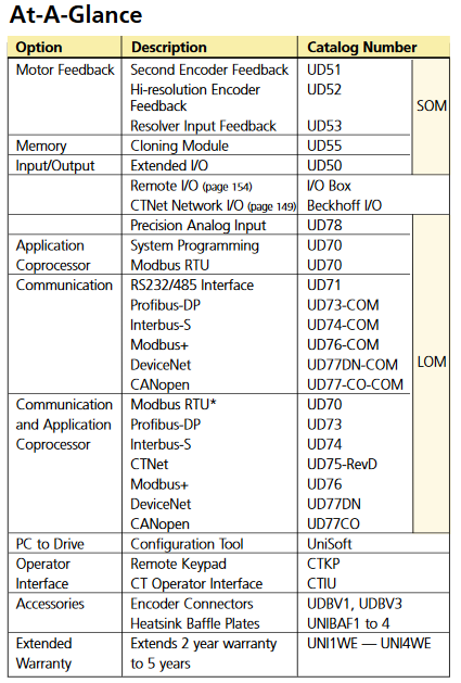
The table below shows a quick reference for all of the different option modules that can be used with the Unidrive Classic series. We have all of the different modules available and in stock.

UD73 Table
UD73 Table

Assigning a 140 NOE Module Ethernet Address Parameter

140NOE77101
140NOE77101

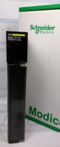
If you have just received the Schneider 140 NOE 771 xx module but have not yet programmed it with an Ethernet configurable extension, you will need to assign an IP address to your module. In this guide you’ll receive information about assigning a 140 NOE Module Ethernet Address Parameter.
Using the BOOTP Lite software utility you can assign IP address parameters. One thing to note, however, is that with the modules 140 NOE 771 01, -11, and NWM 100 00 you can assign the IP address using web pages.

Read More