6FC5357-0BB35-0AA0 Configuration and Setup

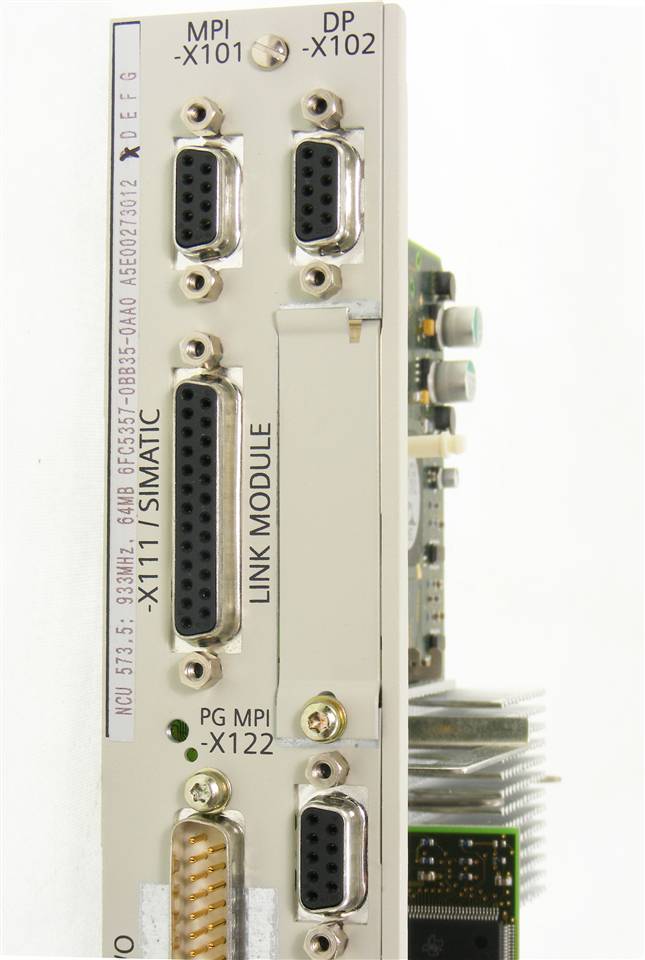
You can check out our previous blog post on the 6FC5357-0BB35-0AA0 here for more information. Check out our websites to see all of our Siemens products.

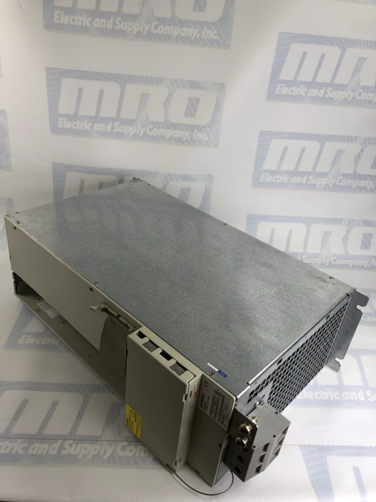
The 6FC5357-0BB35-0AA0 configuration features a modular design comprising line filter, commutating reactor, line supply infeed module, drive modules as well as, when required: monitoring, pulsed resistor and capacitor module(s). Satisfactory operation is ensured only in conjunction with the components that are described in the 6FC5357-0BB35-0AA0 Configuration Manual or published in the Catalog NC60 (Internet Mall) and with adherence to the required boundary/application conditions. Modules can also be arranged in several tiers one above the other or next to one another.

The housings of the  6FC5357-0BB35-0AA0 converter system modules are enclosed and EMC–compatible as specified in EN 60529 (IEC 60529). The electrical system is designed to comply with EN 50178 (VDE 0160) and EN 60204, and an EC declaration of conformity is available. The connections in the module group, motor cables, encoder lines and bus lines must be made using preassembled MOTION–CONNECT lines.

Due to the limited conductivity of the DC link busbars of the modules with module width 150 mm, the DC link power PZK of these modules must not exceed 55 kW. Larger DC link busbars must be used if this restriction cannot be complied with. The DC link power PZK of the subsequent modules is calculated according to the engineering rule specified in the manual. The larger DC link busbars can be ordered as a set. The set includes reinforced DC link busbars for module widths 50 mm, 100 mm and 150 mm. The standard DC link brackets between the modules may not be changed, even when strengthened DC link busbars are used.

To order or get price you can email sales@mroelectric.com or call 1-800-691-8511.

6FC5357-0BB35-0AA0
6FC5357-0BB35-0AA0 Configuation

UNI3405 Configuration and Setup

You can check out our previous blog post on the Control Techniques UNI3405 manual here for more information.

Since capacitance in the motor cable causes loading on the output of the UNI3405 Drive, ensure the cable length does not exceed 660 ft. (400 volts) or 410 ft. (480 volts).
Cable lengths in excess of the specified values may be used in the UNI3405 configuration only when special techniques are adopted; refer to the supplier of the Drive.

The maximum cable length  for the Unidrive UNI3405 configuration is reduced from that shown above under the following conditions:

    • PWM switching frequency exceeding 3kHz in model sizes 3 and 4 — The maximum cable length is reduced in proportion to the increase in PWM switching frequency, eg. at 9kHz, the maximum length is 1/3 of that shown.
  • High-capacitance cables – Most cables have an insulating jacket between the cores and the armour or shield; these cables have a low capacitance and are recommended. Cables that do not have an insulating jacket tend to have high capacitance; if a cable of this type is used, the maximum cable length is half that quoted in the table.
The Drive has two forms of thermal protection for the power output stage (IGBT bridge), as follows:
  1. A thermistor mounted on the heatsink monitors the heatsink temperature. If this exceeds 95 °C (203 °F), the thermistor will cause the Drive to trip. The display will indicate Oh2
  2. Intelligent thermal modelling estimates (by calculation) the junction temperature of the IGBTs. There are two temperature thresholds which cause the following to occur:
    • If the first threshold is reached, the PWM switching frequency is halved in order to reduce dissipation in the IGBTs. (When the frequency is halved, the value of parameter 0.41 PWM switching frequency remains at the value set by the user; if the frequency is 3kHz or 4.5kHz, no halving occurs). Then at one second intervals, the Drive will attempt to restore the original PWM switching frequency. This will be successful if the estimated temperature has reduced sufficiently.
    • If the estimated temperature has continued to rise and reaches a second threshold, the Drive will trip. The display will indicate Oh1.

You can get price and availability by emailing sales@mroelectric.com or calling 1-800-691-8511.

uni3405
Control Techniques uni3405

6SN1145-1BA01-0BA1 Configuration and Setup

You can view our previous blog post on the Siemens 6SN1145-1BA01-0BA1 manual here for more information.

Drive Line-Up
The Siemens 1P 6SN1145-1BA01-0BA1 configuration is modular, comprising line filter, commutating reactor, line supply infeed module, drive modules as well as, when required: monitoring, pulsed resistor and capacitor module(s). Satisfactory operation is ensured only in conjunction with the components that are described in the Configuration Manual or published in the Catalog NC60 (Internet Mall) and with adherence to the required boundary/application conditions. In order to avoid contamination, the modules should be installed in a control cabinet with degree of protection IP 54. Modules can also be arranged in several tiers one above the other or next to one another.

Check out all of our Siemens products on our website!

Due to the limited conductivity of the DC link busbars of the modules with module width 150 mm, the DC link power PZK of the Siemens 6SN1145-1BA01-0BA1 configuration must not exceed 55 kW. Larger DC link busbars must be used if this restriction cannot be complied with. The DC link power PZK of the subsequent modules is calculated according to the engineering rule specified in Chapter 1.3 of the manual. The larger DC link busbars can be ordered as a set with Order No. [MLFB] 1P 6SN1161–1AA02–6AA0. The set includes reinforced DC link busbars for module widths 50 mm, 100 mm and 150 mm. The standard DC link brackets between the modules may not be changed, even when strengthened DC link busbars are used.

For a 6SN1161–1AA02–6AA0 price quote and ordering info you can email sales@mroelectric.com or call 1-800-691-8511.
6SN1145-1BA01-0BA1 Configuration
Siemens 6SN1145-1BA01-0BA1 Configuration
UNI1405

UNI1405 Configuration and Setup

You can check out our previous blog post on the UNI1405 parameters and manual here with additional setup info. Check out our entire collection of Unidrives on our website.

With the UNI1405 configuration, the volts / frequency ratio must be kept constant to ensure rated torque is available from the motor over the frequency range. At low frequencies (from 0 Hz to ½ x Pr 5.06) the voltage is increased from this characteristic by a level governed by either the voltage boost parameter or the motor parameters (found during the stator resistance test) depending on whether the drive is in fixed boost or open loop vector mode as shown aside.

UNI1405 Motor Rated Power Factor

The power factor is found by the UNI1405 4kw during the autotune procedure. It is used in the open loop vector algorithm and to set the current limit levels for the torque producing (active) current.

Emerson UNI1405 4kw Motor Rated Speed

The motor rated speed parameter should be set to the synchronous speed of the motor minus the slip speed. This is often displayed on the motor nameplate. I.e. For a typical 18.5 kW, 50 Hz, 4 pole motor the motor rated speed is 1465 rpm. The synchronous speed for a 4 pole motor is 1500 rpm therefore the slip speed is 35 rpm Synchronous speeds for different numbers of poles are as follows:
2 pole = 3,000 rpm
4 pole = 1,500 rpm
6 pole = 1,000 rpm
8 pole = 750 rpm
The accuracy of this parameter is very important as it directly affects the torque produced at the shaft. Often the value given on the motor nameplate is not
100% accurate which can lead to a loss of torque.
For ordering info or a UNI1405 price you can call 1-800-691-8511 or email sales@mroelectric.com.
UNI1405 Configuration

6SN1123-1AA00-0EA1 Configuration and Setup

The steps for 1p 6SN1123-1AA00-0EA1 Manual Configuration and Setup are below as a follow up to our previous entry here.
 
Start-up Possibilities for 1p 6SN1123-1AA00-0EA1 Configuration
using
- operator control and display elements (refer to Section 1.3)
- RS232C interface with an IBM AT–compatible computer and start–up soft-
ware
 
Re-initialize Drive Converter (if required)
If an already initialized drive–converter is to be re–initialized, then proceed as
follows:
- if required, back–up the setting data (parameters)
- remove write protection: Set P–051 to 4H
- start initialization: Set P–097 to 0H
- overwrite the parameters in the drive–machine data memory: Set P–052 to 1H, and wait until P–052 resets itself to 0H.
- power–on reset:
Power–down the unit and power–up approximately 2 s after the display has disappeared:
P–095 must then appear in the display.
- initialize
 
Firmware Replacement (if required)
The firmware can be replaced using the user–prompted start–up software for
main spindle– and induction motor modules, from version V2.00.
 
Firmware release
before FW 3.00 -> 6SN1121–0BA1_–0AA0
from FW3.00 -> 6SN1121–0BA11–0AA1
 
Procedure:
- back–up setting data (parameters)
- replace the firmware using the start–up program
- initialize with the pulses and controller inhibited
- re–load the backed–up settings
- back–up the setting data in the drive–machine data memory
 
Start-up of series machines, module replacement, component replacement
The drive converter setting data (parameters) can be saved on floppy disk using
the start–up software. Proceed as follows to start–up additional drive converters
(start–up of series machines):
1.Initialize with the pulses and controllers inhibited:
Enter P–095 power module code number
– Motor code number and motor encoder pulse number are saved on the floppy disk, and therefore do not have to be entered.
– Start initialization.
2. Load and save the setting data from the floppy disk.
 
For more info or a 1p 6SN1123-1AA00-0EA1 price you can email sales@mroelectric.com or call 1-800-691-8511.

UNI2403 Configuration and Setup

The UNI2403 and UNI2403-r configuration process is a relatively simple setup process that should be able to get you back up and running with minimal downtime.

With some simple UNI2403 11kw configuration the drive can be used as an AC Regenerative Unit, also known as a Regen Drive. In the case of a drive operating in Regen mode, the IGBT bridge is used as a sinusoidal rectifier, which converts the AC supply to a controlled DC voltage. This DC voltage can then be used to supply one or more Unidrives which control motors, commonly known as motoring drives.

A regen drive produces PWM output voltage which has a sinusoidal fundamental at an amplitude and phase which are almost the same as those of the AC supply voltage. The difference between the drive PWM line voltage and the supply voltage occurs across the Regen drive’s inductors.

There are a number of possible options available when designing a Unidrive Regen system depending on the user requirements and the nature of the AC supply. Non standard systems can be created where favourable supply conditions exist, allowing cost and space savings to be achieved by reducing the number of components.

A Unidrive can be used as a sinusoidal input current power unit to supply one or more Unidrives via their DC buses. When this mode is selected as the drive type, menu 15 appears. This menu is used to set up the Unidrive. At the same time, menu 0 defaults to showing Pr 15.01 to Pr 15.13 as Pr0.11 to Pr 0.28.

You can check out our previous blog post on the UNI2403 manual and UNI2403-r manual here with additional setup info. To get a UNI2403 price quote or for ordering info you can call 1-800-691-8511 or email sales@mroelectric.com.

UNI3405: Beyond the User Manual Parameters

The UNI3405 Unidrive is part of the Classic Unidrive series. Control Techniques introduced the Unidrive Classic around 1993 in Europe and approximately 1995 in the Americas. Because the Unidrive Classic ran simple Open Loop, Closed Loop Vector, and Servo motor applications as well as offering a Regen mode, the UNI3405 found its way into a great many industrial applications, from simple to quote complex. Visit our website to checkout all of our Control Techniques products.

Due to its status as a legacy product, the UNI3405 is becoming available only in limited quantities.

The UNI3405 contains approximately 500-600 parameters that help machine manufacturers achieve the desired functionality for a certain machine requirement. Some applications may require 20-30 or more parameters to be changed from the drives factory default settings. Should drive replacement become necessary, one must have a complete and accurate list of these parameters so that the original functionality can be restored. If you do not have a list of the required parameters, one could copy down these parameters manual. This is assuming that the drive still works enough to power the display, and even then the manual copying of parameters is tedious and error prone.

For more info you can visit our product page here. You can get price and availability by emailing sales@mroelectric.com or calling 1-800-691-8511.

UNI3405
UNI3405