Control Techniques UNIDRIVE Alarm and Status Indications

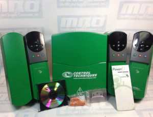
Control Techniques Unidrives

When there is a critical condition detected in your Control Techniques UNIDRIVE, the drive will continue to operate, but the lower display’s status indication will be replaced by an alarm indication. When an HF trip takes place, the Drive Healthy relay will open and serial communications will not function. It is important to give attention to alarm indications, because if an issue is not corrected, the drive could trip.

Refer to the guide below to help identify what kind of error your UNIDRIVE may be experiencing. A comparison chart with status indications is also provided to help identify what happens at each stage of operation.
Read More

A06B-6117-H211 Alarm Code Troubleshooting

 List of A06B-6117-H211 Alarm codes that should help you with troubleshooting. If you do decide you need more help or want to replace your unit, give us a call at 800-691-8511 or email sales@mroelectric.com. You can also visit our product page for the A06b-6117-H211 for more info, or check out all of our FANUC motors and drives.
Alarm Code 1
      (1)Meaning Inverter: internal cooling fan stopped
      (2)Cause and troubleshooting
              (a)Check whether there is any foreign material in the fan.
              (b)Check that the fan connector is attached correctly.
              (c)Replace the fan.
              (d)Replace the SVM.
Alarm Code 2
     (1)Meaning Inverter: control power supply under voltage
     (2)Cause and troubleshooting
              (a)Check the three-phase input voltage of the amplifier (the voltage shall not be lower than 85% of the rated input voltage).
              (b)Check the 24 V power supply voltage output from the PSM (the voltage shall normally not lower than 22.8 V).
             (c)Check the connector and cable (CXA2A/B).
             (d)Replace the SVM.
Alarm Code 5
      (1)Meaning Inverter: DC
link under voltage
      (2)Cause and troubleshooting
              (a) Check that the screws for the DC link connection cable (bar) are tight.
              (b)If a DC link low voltage alarm condition occurs in more than one module, see Subsection 3.1.4, “Alarm code 4” for explanations about how to troubleshoot the power supply module.
              (c)If a DC link low voltage alarm condition occurs in only one SVM, replace that SVM.
Alarm Code 6
     (1)Meaning Inverter: overheat
     (2)Cause and troubleshooting
            (a)Check that the motor is being used at or below its continuous rating.
            (b)Check that the cooling capacity of the cabinet is sufficient (inspect the fans and filters).
            (c)Check that the ambient temperature is not too high.
            (d)Replace the SVM.
Alarm Code F
     (1)Meaning Inverter: cooling
fan stopped of the radiator
     (2)Cause and troubleshooting
          (a)Check whether there is any foreign material in the fan.
          (b)Check that the fan connector is attached correctly.
          (c)Replace the fan.
          (d)Replace the SVM.
Alarm Code P
     (1)Meaning Communication error between amplifier and module
     (2)Cause and troubleshooting
          (a)Check the connector and cable (CXA2A/B).
          (b)Replace the control printed-circuit board.
          (c)Replace the SVM.
Alarm Code 8
     (1)Meaning Inverter: DClink current alarm
     (2)Cause and troubleshooting
           (a)Disconnect the motor power leads from the SVM, and release the SVM from an emergency stop condition.
              <1>If no abnormal DC link current alarm condition has occurred. Go to (b).
             <2>If an abnormal DC link current alarm condition has occurred. Replace the SVM.
          (b)Disconnect the motor power leads from the SVM, and check the insulation between PE and the motor power lead U, V, or W.
                 <1>If the insulation is deteriorated. Go to (c).
                 <2>If the insulation is normal. Replace the SVM.
         (c)Disconnect the motor from its power leads, and check whether the insulation of the motor or power leads is deteriorated.
                <1>If the insulation of the motor is deteriorated. Replace the motor.
                <2>If the insulation of any power lead is deteriorated. Replace the power lead.
Alarm Code 8.9.A.
     (1)Meaning Inverter: IPM alarm
     (2)Cause and troubleshooting
             (a)Disconnect the motor power leads from the SVM, and release the SVM from an emergency stop condition.
                   <1>If no IPM alarm condition has
occurred. Go to (b).
                   <2>If an IPM alarm condition has occurred. Replace the SVM.
            (b)Disconnect the motor power leads from the SVM, and check the insulation between PE and the motor power lead U, V, or W.
                   <1>If the insulation is deteriorated. Go to (c).
                   <2>If the insulation is normal. Replace the SVM.
            (c)Disconnect the motor from its power leads, and check whether the insulation of the motor or power leads is deteriorated.
                   <1>If the insulation of the motor is deteriorated. Replace the motor.
                    <2>If the insulation of any power lead is deteriorated. Replace the power lead.
Alarm Code 8.9.A.
     (1)Meaning Inverter: IPM alarm (OH)
     (2)Cause and troubleshooting
             (a)Check that the heat sink cooling fan is running.
             (b)Check that the motor is being used at or below its continuous rating.
             (c)Check that the cooling capacity of the cabinet is sufficient (inspect the fans and filters).
             (d)Check that the ambient temperature is not too high.
             (e)Replace the SVM.
Alarm Code bcd
       (1)Meaning Abnormal inverter motor current
       (2)Cause and troubleshooting
              (a)Checking the servo parameters Referring to “FANUC AC SERVO MOTOR i series Parameter Manual (B-65270EN),” check whether the following parameters have default values.
Fanuc-15i PRM 1809, 1852, 1853
Fanuc-16i/18i/21i PRM & Power Mate i No.2004, 2040, 2041
For more help or a quote to replace your unit, give us a call at 800-691-8511 or email sales@mroelectric.com.

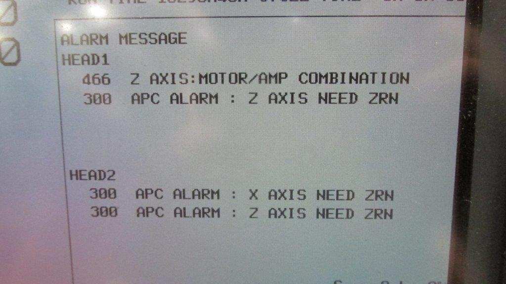
Fanuc Alarm 466 – Z Axis: Motor/Amp Combination

We just shipped out a Fanuc A06B-6096-H207 Servo Amp unit to a customer, and as soon as they installed the amplifier they got a Fanuc Alarm 466 which refers to the Z Axis: Motor/Amp Combination. This is obviously somewhat distressing for a customer to buy a replacement unit and immediately get an alarm when it is installed, but fortunately this is an easy fix.

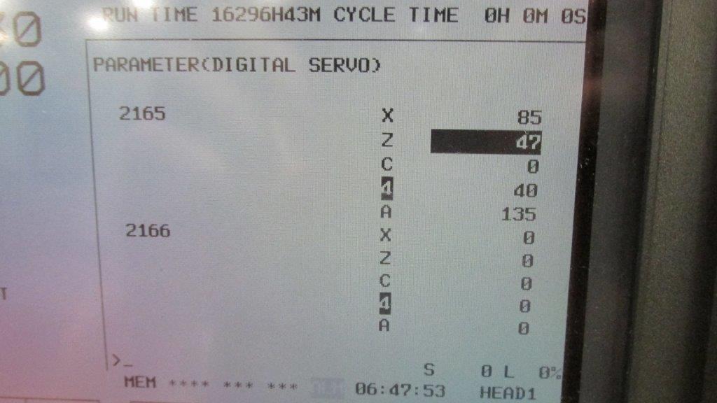
This Alarm 466 comes from the replacement amplifier having newer servo software than the unit that it is replacing. As Fanuc has made newer units they’ve upgraded the software/hardware within these amplifiers, so you just need to reset a parameter to reboot the configuration and clear the 466 Alarm. The steps are below.

– Put the machine in Emergency Stop
– Go to parameter 2165 on the control
– Set all the values to 0
– Take the machine out of emergency stop

Once these parameters are changed and the machine is rebooted, the alarm will clear and the amplifier will initialize. We also have pictures below to confirm that you know what to look for. For any additional help, call us at 800-691-8511 or email sales@mroelectric.com.

FANUC Alarm 466
FANUC Alarm 466
FANUC Alarm 466
FANUC Alarm 466
MRO Electric stocks a large number of FANUC CNC Products, and provides repair services as well. For more information or to request a quote, please call 800-691-8511 or email sales@mroelectric.com.

Simodrive E/R Module Fault – Troubleshooting

We had a customer who was getting an alarm on their Simodrive E/R Module with a fault on the machine after the hydraulic was put on. They had tried resetting the machine but the same alarm would come back up. The Simodrive part number was 6SN1145-1BA01-0DA1, the only light on it was the green LED and the terminals were both reading 27VDC. The customer was considering buying a new drive but wanted to check to see if there was some way of resolving the issue without buying a whole new Simodrive.

Based off the LED configuration that the customer was having, we determined that the external enable signal 63 was missing, so they needed to double check their connections. When the customer checked, the contact from the hydraulic connector was not making a good connection. All the customer needed to do was replace the contact kit and restart the machine which got them up and running. We would highly recommend always double checking the connections on a unit before replacing it, because there can often be a simple issue that doesn’t require the full unit to be replaced.

Contact MRO Electric and Supply at (800)691-8511 or email us at sales@mroelectric.com about repair services.

Fanuc Spindle Amp Alarm Codes for Alpha Series

fanuc spindle amp

Fanuc Spindle Amp Alarm Codes for Alpha Series

Fanuc Spindle Amp Alarm codes for amplifiers that start with part number A06B-6088, A06B-6102, and A06B-6078.

“A” Program Rom abnormality (Not Installed)

AL-01 Motor Overheat

AL-02 Excessive speed deviation

AL-03 DC Link fuse blown

AL-04 Input fuse blown

AL-05 Control power supply

AL-06 Over Speed

AL-07 Excessive Speed

AL-08 High Input Voltage

AL-09 Excessive load on main circuit section

AL-10 Low input voltage

AL-11 Over-voltage in DC link section

AL-12 Over-current in DC link section

AL-13 CPU Internal data memory abnormality

AL-15 Spindle switch/output switch alarm

AL-16 RAM Abnormality

AL-18 Program ROM checksum error

AL-19 Excessive U phase current detection circuit offset

AL-20 Excessive V phase current detection circuit offset

AL-24 Serial transfer data error

AL-25 Serial transfer data stopped

MRO Electric and Supply maintains a comprehensive stock of new and used FANUC CNC parts including FANUC Spindle Amps. If you need a replacement part, please call 800-691-8511 or email sales@mroelectric.com.

AL-26 Disconnection of speed detection signal for C’s contouring control

AL-27 Position coder signal disconnection

AL-28 Disconnection of position detection signals for C’s contouring control

AL-29 Short-time overload

AL-30 Input circuit over current

AL-31 Speed detection signal disconnection motor restraint alarm

AL-32 Abnormality in RAM internal to LSI for serial data transfer

AL-33 Insufficient DC link section charging

AL-34 Parameter data setting beyond allowable range of values

AL-35 Excessive gear ratio data setting

AL-36 Error counter overflow

AL-37 Speed detector parameter setting error

AL-39 Alarm for indicating failure in detecting 1-rotation signal for C’s contouring control

AL-40 Alarm for indicating 1-rotation signal for C’s contouring control not detected

AL-41 Alarm for indicating failure in detecting position coder 1-rotation signal

AL-42 Alarm for indication position coder 1-rotation not detected

AL-43 Alarm for indicating disconnection of position coder signal for differential speed mode

AL-46 Alarm for indicating failure in detecting position coder 1 rotation signal in thread cutting operation

AL-47 Position coder signal abnormality

AL-48 Position coder 1-rotation signal abnormality

AL-49 The converted differential speed is too high

AL-50 Excessive speed command calculation value in spindle synchronization control

AL-51 Under voltage at DC link section

AL-52 ITP signal abnormality 1

AL-53 ITP signal abnormality 2

AL-54 Overload current alarm

AL-55 Power line abnormality in spindle switching/output switching

AL-56 Cooling fan error.
Simodrive F15 Alarm Code – Cause and Solution

Recently a customer sent in a Siemens Simodrive for repair when they were getting an F15 Alarm on the unit. The description for this alarm is as follows:

– F–15 Drive converter
– Overtemperature
     – Drive converter overloaded
(incorrect motor/converter assignment, incorrect load duty cycle,
clock cycle frequency too high)
      – Ambient temperature too high
      – Fan in the IM module failed
      – Defective temperature sensor in the IM module

Normally, this Simodrive F15 Alarm is in reference to the fans in the unit failing, which in turn causes an over temperature issue in the unit. This is normally caused by the fans not being cleaned out regularly which causes them to jam, which can then short out other internal boards in the unit. This was the case for the unit the customer sent in, so we took apart the unit, replaced the fans, and replaced several internal boards that had shorted. We would highly recommend routine cleaning of Simodrive fans, especially dirty ones, to prevent drive failure.

MRO Electric and Supply supplies and repairs a large number of Siemens Simodrives. To request a quote, please call 800-691-8511 or email sales@mroelectric.com.