Mastering CNC Maintenance: 15 Essential Tips for Peak Performance

Computer Numerical Control (CNC) machines are essential tools in modern manufacturing and machining. These precision instruments can perform complex tasks with incredible accuracy. However, like any machinery, CNC machines require regular maintenance to ensure they operate efficiently and reliably. In this comprehensive guide, we’ll explore 15 essential tips for CNC maintenance to keep your equipment in optimal condition.

Chapter 1: Daily Maintenance

  1. Cleanliness is Crucial Maintaining a clean CNC machine is paramount. Dust, chips, and debris can lead to performance issues and wear on critical components.
    • Start each day by blowing away chips and dust with compressed air.
    • Wipe down surfaces with a clean, lint-free cloth.
    • Ensure that coolant and lubrication systems are clean and free from contamination.
  2. Inspect Toolholders and Workholding Devices Check toolholders, collets, and workholding devices daily for signs of damage or wear. Replace any components that appear compromised to maintain precise tool alignment.
  3. Lubrication Most CNC machines require regular lubrication. Refer to the manufacturer’s manual for a lubrication schedule and be precise in your application. Over- or under-lubrication can lead to problems.

Chapter 2: Weekly Maintenance

  1. Examine Way Covers and Bellows Way covers and bellows protect critical machine components from contaminants. Inspect them weekly for damage or leaks and replace any compromised parts to prevent issues.
  2. Spindle and Taper Maintenance Clean the spindle and taper thoroughly, removing debris or buildup. Inspect for wear and have them professionally serviced or replaced if necessary.
  3. Check Electrical Connections Regularly inspect all electrical connections, wires, cables, and connectors for wear or loose connections. Reliable electrical connections are crucial for CNC machine performance and safety.
Read More

Common UNI1405 Fault Codes

Below is a table of common Unidrive faults found within the Control Techniques Unidrive series, more specifically, the UNI1405. MRO Electric offers core credit on exchanges for new and refurbished units, and have a wide selection of option cards such as the UD51, UD73, and UD77. We also repair Unidrives in-house. Contact us if you are interested in finding a new machine so we can keep your downtime to a minimum!

HF81Software Error (odd address word)
HF82Large option module removed
HF83Power Board Code Failure
HF84Current Offset Trim Failure
HF85A to D failure (ES-CC step)
HF86Interrupt Watchdog failure
HF87Internal ROM check error
HF88Watchdog Failure
HF89Unused Interrupts (nmi as source)
HF90Stack Overflow
HF91Stack Underflow
HF92Software Error (undefined op code)
HF93Software Error (protection fault)
HF94Software Error (odd address word)
HF95Software Error (odd address inst.)
HF96Software Error (illegal ext bus)
HF97Level 1 Noise
HF98Interrupt Crash
HF99Level 1 Crash
Sinamics S120

Sinamics S120 Fault Codes and Alarms, Part I

It is important to understand the differences between faults and alarms on Sinamics S120 Drives by Siemens. We have included a list of common faults and alarm codes for S120 drives, what they mean, likely causes and how to fix the fault or alarm. For more Sinamics S120 faults and alarms, check out Part II and Part III of the series that we will be posting shortly. Be sure to check out our website to browse all of our Siemens products.

Understanding Faults 

Sinamics S120 Fault Codes Numerical Ranges

When operating Sinamics S120, various errors can arise that may impact the machine’s performance. These faults are typically accompanied by error messages. The fault codes for Sinamics S120 are organized into numerical ranges, each corresponding to a specific type of issue:

  • F0001 – F0099: Control unit
  • F0100 – F0199: Reserved
  • F0200 – F0299: Power supply
  • F0300 – F0399: Feed unit
  • F0400 – F0499: Drive
  • F0500 – F0599: Option board
  • F0600 – F2999: Reserved
  • F3000 – F3099: DRIVE-CLiQ component power section
  • F3100 – F3199: DRIVE-CLiQ component encoder 1
  • F3200 – F3299: DRIVE-CLiQ component encoder 2
  • F3300 – F3399: DRIVE-CLiQ component encoder 3
  • F3400 – F3499: Reserved
  • F3500 – F3599: Terminal Module 31
  • F3600 – F4999: Reserved
  • F5000 – F5039: Communication Board (COMM BOARD)
  • F5040 – F65535: Reserved

This classification aids in swiftly identifying the type of problem based on the fault code range, making troubleshooting more efficient.

What happens when a fault occurs?

  • The appropriate fault reaction is initiated
  •  Status signal ZSW1.3 is set.
  • The fault is entered in the fault buffer.

How are faults eliminated?

  • Remove the original cause of the fault
  • Acknowledge the fault

Understanding Alarms

What happens when an alarm occurs?

  • Status signal ZSW1.7 is set.
  • Alarms are “Self Acknowledging” meaning they are reset when the cause of the alarm has been eliminated.

List of Sinamics S120 Faults and Alarms

F01000:  Internal software error

Message Value: Module: %1, Line: %2
Drive Object: All Objects
ReactionOFF2
AcknowledgePOWER ON
Cause: An internal software error has occurred. Fault value (r0949, interpret hexadecimal)
Remedy

  • Evaluate fault buffer
  • Carry out a POWER ON (power on/off) for all components.
  • If required, check the data on the non-volatile memory (memory card).
  • Upgrade firmware to a later version.
  • Replace the control unit or contact MRO Electric.

F01001:  Floating Point Exception

Message Value: %1
Drive Object: All objects
Reaction: OFF2
AcknowledgePOWER ON
Cause: An exception occurred during an operation with the FloatingPoint data type. The error may be caused by the basic system or the OA application (e.g. FBLOCKS, DCC).
Remedy:

  • Carry out a POWER ON (power on/off) for all components.
  • Check configuration and signals of the blocks in FBLOCKS.
  • Check configuration and signals of DCC charts.
  • Upgrade firmware to a later version.
  • Contact Service Hotline.

F01002:  Internal software error

Message Value: %1
Drive Object: All objects
Reaction: OFF2
Acknowledge: IMMEDIATELY
Cause: An internal software error has occurred
Remedy: 

  • Carry out a POWER ON (power on/off) for all components.
  • Upgrade firmware to a later version.
  • Contact Service Hotline.

F01003:  Acknowledgement delay when accessing the memory

Message Value: %1
Drive Object: All objects
Reaction: OFF2
Acknowledge: IMMEDIATELY
Cause: A memory area was accessed that does not return a “READY”.
Remedy: 

  • Carry out a POWER ON (power on/off) for all components.
  • Contact Service Hotline

N01004 (F, A):  Internal software error

Message Value: %1
Drive Object: All objects
Reaction: NONE
Acknowledge: NONE
Cause: An internal software error has occurred. 
Remedy:  Read out diagnostics parameter (r9999).
Reaction upon F: OFF2
Acknowl. upon F: POWER ON
Reaction upon A:  NONE
Acknowl. upon A: NONE

F01005:  Firmware  download for DRIVE-CLiQ component unsuccessful

Message Value: Component number: %1, fault cause: %2
Drive Object: All objects
Reaction: NONE
Acknowledge: IMMEDIATELY
Cause: It was not possible to download the firmware to a DRIVE-CLiQ component
Remedy:

  • Check the selected component number
  • Check the DRIVE-CLiQ connection
  • Save suitable firmware file for download in “/siemens/sinamics/code/sac/”
  • Use a component with a suitable hardware version
  • After POWER ON has been carried out again for the DRIVE-CLiQ component,                               download the firmware again. Depending on p7826, the firmware will be                                       automatically downloaded.

A01006: Firmware update for DRIVE-CLiQ component required

Message Value: Component number: %1
Drive Object: All objects
Reaction: NONE
Acknowledge: NONE
Cause: The firmware of a DRIVE-CLiQ component must be updated as there is no suitable firmware or firmware version in the component for operation with the Control Unit.
Alarm value (r2124, interpret decimal): Component number of the DRIVE-CLiQ component
Remedy: 

  • Firmware update using the commissioning software:
    • The firmware version of all of the components on the “Version overview” page can be read in the Project Navigator
      under “Configuration” of the associated drive unit and an appropriate firmware update can be carried out.
  • Firmware update via parameter:
    • Take the component number from the alarm value and enter into p7828.
    • Start the firmware download with p7829 = 1.

A01007: POWER ON for DRIVE-CLiQ component required

Message Value: Component number: %1
Drive Object: All objects
Reaction: NONE
Acknowledge: NONE
Cause: A DRIVE-CLiQ component must be powered up again (POWER ON) (e.g. due to a firmware update). 

Alarm value (r2124, interpret decimal): Component number of the DRIVE-CLiQ component. If the component number is 1, a POWER ON of the Control Unit is required. 
Remedy: 

  • Switch off the power supply of the specified DRIVE-CLiQ component and switch it                   on again.
  • For SINUMERIK, auto commissioning is prevented. In this case, a POWER ON is                           required for all components and the auto commissioning must be restarted.

A01009 (N):   CU: Control module overtemperature

Message Value: –
Drive Object: All objects
Reaction: NONE
Acknowledge: NONE
Cause: The temperature (r0037[0]) of the control module (Control Unit) has exceeded the specified limit value.
Remedy:

  • Check the air intake for the Control Unit.
  • Check the Control Unit fan.

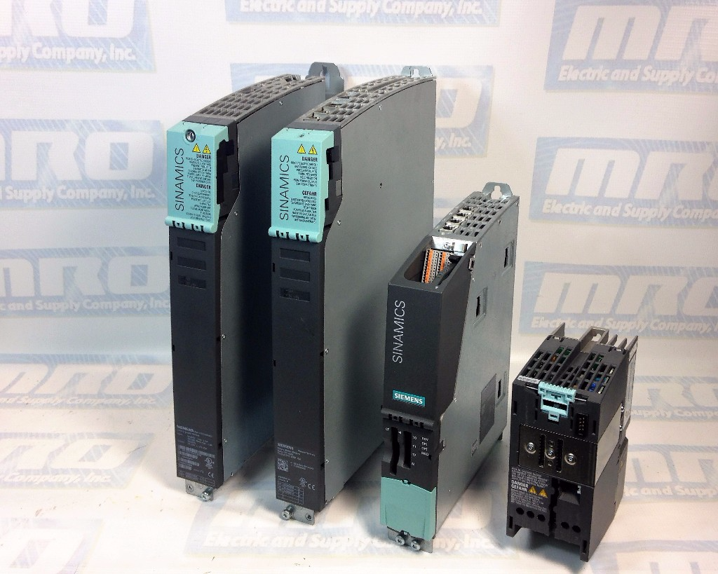
MRO Electric and Supply carries new and used Sinamics modules. For more information or to request a quote, call 800-691-8511 or email sales@mroelectric.com.

Dealing with Sinamics S120 Fault Codes?

Fault codes on your Sinamics S120 can be a major setback. MRO Electric provides the expertise and parts you need to diagnose and resolve issues swiftly, ensuring your drive system runs smoothly without extended downtime.

FANUC Controls Alarms

Fanuc Power Supply Alarm Codes – Alpha Series

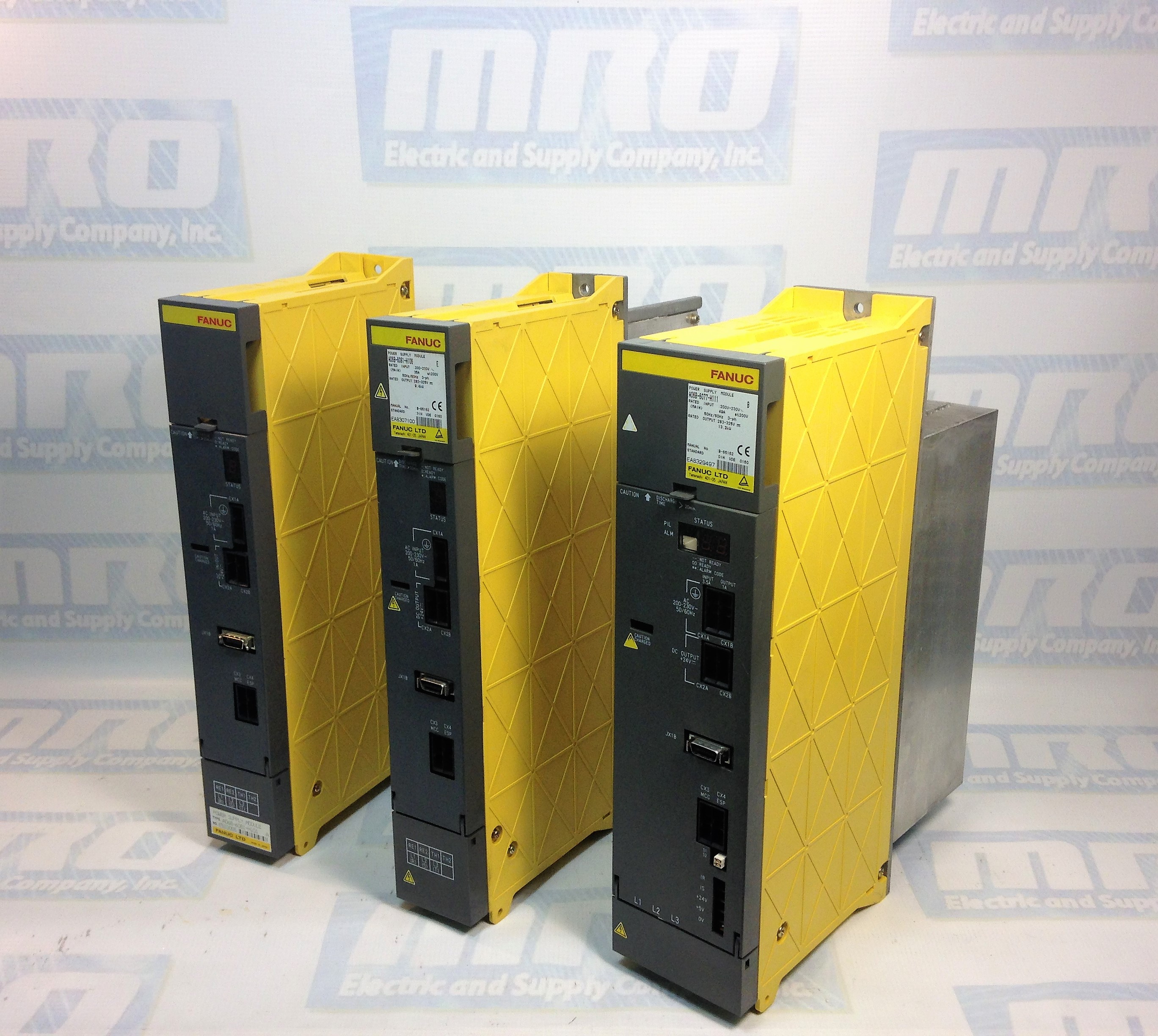
Recently we had a customer who was working on troubleshooting a FANUC CNC Power Supply alarm that he had on a machine. He was wondering what the different codes stood for, so we wanted to go ahead and list the different alarm codes for this series. These codes apply to power supplies that start with the following prefixes. The “X”s after the H will be numbered, so an example part number is A06B-6087-H130.

A06B-6081-HXXX
A06B-6083-HXXX
A06B-6077-HXXX
A06B-6091-HXXX
A06B-6120-HXXX
A06B-6140-HXXX
A06B-6110-HXXX

Here is a list of the alarm codes for these series of Power Supply Modules.

AL01: The main circuit power module (IPM) has detected am Error (PSM-5.5,-11)
Overcurrent flows into the input of the main circuit (PSM-15 to –30).

AL02: A cooling fan for the control circuit has stopped.

AL03: The Temperature of the main circuit heat sink has risen abnormally.

AL04: In the main circuit the DC voltage (DC Link) has dropped.

AL05: The main circuit capacitor was not recharged within the specified time.

AL06: The Input Power Supply is abnormal (open phase).

AL07: In the main circuit the DC Voltage at the DC link is abnormally high.

Be sure to check out our article covering FANUC CNC Troubleshooting Frequently Asked Questions here.

A06B-6087-H130 alarm codes

For more information or to get a quote on a FANUC power supply, please call 800-691-8511 or email sales@mroelectric.com.

We also provide repair services for FANUC Power Supplies.

MagneTek GPD503 Fault Codes

Below is a chart with fault codes regarding the MagneTek G3 GPD503 series drives. MRO Electric and Supply offers free evaluations on units. You can find our RMA form on our repair page. Follow us on Twitter @MROElectric for updates on new products and find any deals we may have.

bbExternal Base Block command
Base Block command at multi-function terminal is active, shutting off GPD 503 output (motor coasting). Temporary condition, cleared when input command is removed.
bUSTransmission error
Control data cannot be received normally for longer than 2 seconds.
CALLCommunication ready
Drive is waiting for the PLC to establish communication.
CPF00Transmission error or control function hardware fault (including internal RAM, external RAM or PROM)
Transmission between GPD 503 and remote operator is not established within 5 seconds after the power supply is turned on. (Displayed on the remote operator.)
CPF01Transmission error
Transmission error occurs 2 seconds or more after transmission has first been established.
CPF02Base block circuit failure
GPD 503 failure.
CPF03NV-RAM (S-RAM) fault
GPD 503 failure.
CPF04NV-RAM (BCC, Access Code)
fault
GPD 503 failure. This fault may be caused after changing EPROM chips. Perform a Sn-03 Reset operation to attempt to clear this fault.
CPF05A/D converter failure in CPU
GPD 503 failure.
CPF06Optional connection failure
Improper installation or wiring of option card.
CPF20A/D converter failure
Defective option card.
CPF21Transmission interface card (option) self-analysis function fault
Defective option card. Check option card connector for proper installation.
CPF22Model code fault
Defective option card. Check option card connector for proper installation.
CPF23Mutual-analysis function fault
Defective option card. Check option card connector for proper installation.
EF (blinking)Simultaneous forward and reverse operation commands
Fwd Run and Rev Run commands are both closed for more than 500 ms. Removing one command will allow drive operation.
EF0External fault
GPD 503 is in Stop mode.
EF3Ext. fault signal at term. 3
A fault condition has occurred in the external circuit(s) monitored by the contact providing input to the indicated terminal. If display is steady, GPD 503 is in Stop mode; if display is blinking, the terminal is programmed to allow continued operation after receiving fault input.
EF5Ext. fault signal at term. 5
A fault condition has occurred in the external circuit(s) monitored by the contact providing input to the indicated terminal. If display is steady, GPD 503 is in Stop mode; if display is blinking, the terminal is programmed to allow continued operation after receiving fault input.
EF6Ext. fault signal at term. 6
A fault condition has occurred in the external circuit(s) monitored by the contact providing input to the indicated terminal. If display is steady, GPD 503 is in Stop mode; if display is blinking, the terminal is programmed to allow continued operation after receiving fault input.
EF7Ext. fault signal at term. 7
A fault condition has occurred in the external circuit(s) monitored by the contact providing input to the indicated terminal. If display is steady, GPD 503 is in Stop mode; if display is blinking, the terminal is programmed to allow continued operation after receiving fault input.
EF8Ext. fault signal at term. 8
A fault condition has occurred in the external circuit(s) monitored by the contact providing input to the indicated terminal. If display is steady, GPD 503 is in Stop mode; if display is blinking, the terminal is programmed to allow continued operation after receiving fault input.
ErrConstant write-in fault
Temporary display, in Program mode, indicating that constant setting was not written into EPROM memory.
FAnCooling fan failure
GPD 503 is in Stop mode.
FUFuse blown
DC Bus fuse has cleared. Check for short circuit in output, and check main circuit transistors.
GFGround fault protection
Ground current > approx. 50% of the GPD 503 rated current.
oCOvercurrent
GPD 503 output current exceeds 200% of GPD 503 rated current, or ground fault has occurred, with ground current exceeding 50% of GPD 503 rated current.
oHHeat sink overheated
Fin temperature exceeds 90° C (194° F)
oH2 (blinking)External overheat
External temperature monitoring circuit(s) detected an overtemperature condition and produced an input signal.
oL1Overload
Thermal motor overload protection has tripped.
oL2Overload
GPD 503 overload protection has tripped.
oL3 (blinking)Overload
GPD 503 output torque exceeds the set Overtorque Detection level, but GPD 503 is programmed for continued operation at overtorque detection.
oL3Overload
GPD 503 output torque exceeds the set Overtorque Detection level, and GPD 503 is programmed for coast to stop at overtorque detection.
oPE01kVA constant setting fault
Sn-01 setting is incorrect.
oPE02Constant setting range fault
An-XX, bn-XX, Cn-XX, or Sn-XX setting range fault.
oPE03Constant set value fault
Sn-15 to -18 (multi-function input) set value fault.
oPE04Constant set value fault
PG constant, number of poles, or PG division rate set incorrectly.
oPE10Constant set value fault
Cn-02 to -08 (V/f data) set incorrectly.
oPE11Constant set value fault
One of the following conditions was detected: • Cn-23 > 5 KHz and Cn-24 5 KHz or • Cn-25 > 6 and Cn-24 > Cn-23
ou (blinking)Overvoltage
Internal monitor of DC Bus voltage indicates that input AC power is excessively high, while GPD 503 is in stopped condition.
ouOvervoltage (OV)
Detection level: Approx. 400V for 230V; Approx. 800V for 460V; Approx. 1000V for 575V.
rrRegenerative transistor Failure
Dynamic Braking resistor has failed.
rHBraking resistor unit overheated
Dynamic Braking resistor has overheated.
Uu (blinking)Low voltage (Power UV)
Internal monitor of DC Bus voltage indicates that input AC power is below Undervoltage detection level, while the GPD 503 is in stopped condition.
Uu1 Low voltage (Power UV)Occurs two seconds after detection of low voltage.
Uu2 Low voltage UVControl circuit voltage levels drop below acceptable levels during operation.
Uu3 Low voltage (MC-ANS fault)Main circuit magnetic contactor does not operate correctly.

Yaskawa P1000 Fault Codes

Below is a table of common fault codes found on Yaskawa P1000 units. If problems continue to occur, it may be worth replacing your unit. MRO Electric specializes in Yaskawa repair, as well as unit distribution, if you are interested in obtaining a new or refurbished P1000 unit.

bATDigital Operator Battery Voltage Low - The digital operator battery is low Replace the digital operator battery.
boLBraking Transistor Overload Fault - The wrong braking resistor is installed Select the correct braking resistor.
bUSOption Communication Error - No signal was received from the PLC. Check for faulty wiring.
CE MEMOBUS/Modbus Communication Error - Faulty communications wiring or an existing short circuit.
CEMEMOBUS/Modbus Communication Error - Faulty communications wiring or an existing short circuit.
CPF02A/D Conversion Error - Control circuit is damaged. Replace the control board or the entire drive.
CPF03Control Board Connection Error - Turn off the power and check the connection between the control board and the drive.
CPF06EEPROM Memory Data Error - Turn off the power and check the connection between the control board and the drive.
CPF07Terminal Board Connection Error - Faulty connection between the terminal board and the control board. Turn off the power and reconnect the terminal board.
CPF08Terminal Board Connection Error - Faulty connection between the terminal board and the control board. Turn off the power and reconnect the terminal board.
CPF11Control Circuit Error - Hardware is damaged. Cycle Power. Replace hardware.
CPF12Control Circuit Error - Hardware is damaged. Cycle Power. Replace hardware.
CPF13Control Circuit Error - Hardware is damaged. Cycle Power. Replace hardware.
CPF14Control Circuit Error - Hardware is damaged. Cycle Power. Replace hardware.
CPF15Control Circuit Error - Hardware is damaged. Cycle Power. Replace hardware.
CPF16Control Circuit Error - Hardware is damaged. Cycle Power. Replace hardware.
CPF17Control Circuit Error - Hardware is damaged. Cycle Power. Replace hardware.Control Circuit Error - Hardware is damaged. Cycle Power. Replace hardware.
CPF18Control Circuit Error - Hardware is damaged. Cycle Power. Replace hardware.
CPF19Control Circuit Error - Hardware is damaged. Cycle Power. Replace hardware.
CPF20Control Circuit Error - Hardware is damaged. Cycle Power. Replace hardware.
CPF21Control Circuit Error - Hardware is damaged. Cycle Power. Replace hardware.
CPF22Hybrid IC Error - Hardware is damaged. Cycle Power. Replace hardware.
CPF23Control Board Connection Error - Hardware is damaged. Cycle Power. Replace hardware.
CPF24Drive Unit Signal Fault - The drive capacity cannot be detected correctly. Cycle Power. Replace hardware.
CPF25Terminal Board Not Connected - Hardware is damaged. Cycle Power. Replace hardware.
CPF26Control Circuit Error - Hardware is damaged. Cycle Power. Replace hardware.
CPF27Control Circuit Error - Hardware is damaged. Cycle Power. Replace hardware.
CPF28Control Circuit Error - Hardware is damaged. Cycle Power. Replace hardware.
CPF29Control Circuit Error - Hardware is damaged. Cycle Power. Replace hardware.
CPF30Control Circuit Error - Hardware is damaged. Cycle Power. Replace hardware.
CPF31Control Circuit Error - Hardware is damaged. Cycle Power. Replace hardware.
CPF32Control Circuit Error - Hardware is damaged. Cycle Power. Replace hardware.
CPF33Control Circuit Error - Hardware is damaged. Cycle Power. Replace hardware.
CPF34Control Circuit Error - Hardware is damaged. Cycle Power. Replace hardware.
CPF35Control Circuit Error - Hardware is damaged. Cycle Power. Replace hardware.
CPF40Control Circuit Error - Hardware is damaged. Cycle Power. Replace hardware.
CPF41Control Circuit Error - Hardware is damaged. Cycle Power. Replace hardware.
CPF42Control Circuit Error - Hardware is damaged. Cycle Power. Replace hardware.
CPF43Control Circuit Error - Hardware is damaged. Cycle Power. Replace hardware.
E5SI-T3 Watchdog Timer Error - Data has not been received from the PLC Execute DISCONNECT or ALM_CLR, then issue a CONNECT command or SYNC_SET command.
EF0Option Card External Fault - An external fault condition is present. Check external causes.
EF1External Fault Terminal S1 - An external fault condition is present. Check external causes. Bad S1 Terminal.
EF2External Fault Terminal S1 - An external fault condition is present. Check external causes. Bad S1 Terminal.
EF3External Fault Terminal S1 - An external fault condition is present. Check external causes. Bad S1 Terminal.
EF4External Fault Terminal S1 - An external fault condition is present. Check external causes. Bad S1 Terminal.
EF5External Fault Terminal S1 - An external fault condition is present. Check external causes. Bad S1 Terminal.
EF6External Fault Terminal S1 - An external fault condition is present. Check external causes. Bad S1 Terminal.
EF7External Fault Terminal S1 - An external fault condition is present. Check external causes. Bad S1 Terminal.
EF8External Fault Terminal S1 - An external fault condition is present. Check external causes. Bad S1 Terminal.
ErrEEPROM Write Error - Noise has corrupted data. Cycle power. Correct the parameter.
FAnInternal Fan Fault - Internal cooling fan has malfunctioned. Check for fan operation.
FbHExcessive PID Feedback - PID feedback input is greater than the level set to. Check parameter.
FbLPID Feedback Loss - Check parameter. There is a problem with the feedback sensor.
GFGround Fault - A current short to ground exceeded 50% of rated current on the output side of the drive. Check motor/cables.
LFOutput Phase Loss - Phase loss on the output side of the drive. Check motor/cables.
LF3Power Unit Output Phase Loss 3 - Phase loss on the output side of the drive. Check motor/cables.
nSENode Setup Error - A terminal assigned to the node setup function closed during run.
oCOvercurrent - Output current greater than the specified overcurrent level. Check parameter. Check motor.
oFA01Option Card Fault - The option card connection is faulty. Check connection. Replace hardware.
oFA03Option Card Fault - The option card connection is faulty. Check connection. Replace hardware.
oFA04Option Card Fault - The option card connection is faulty. Check connection. Replace hardware.
oFA05Option Card Fault - The option card connection is faulty. Check connection. Replace hardware.
oFA06Option Card Fault - The option card connection is faulty. Check connection. Replace hardware.
oFA10Option Card Fault - The option card connection is faulty. Check connection. Replace hardware.
oFA11Option Card Fault - The option card connection is faulty. Check connection. Replace hardware.
oFA12Option Card Connection Error - The option card connection is faulty. Check connection. Replace hardware.
oFA13Option Card Connection Error - The option card connection is faulty. Check connection. Replace hardware.
oFA14Option Card Connection Error - The option card connection is faulty. Check connection. Replace hardware.
oFA15Option Card Connection Error - The option card connection is faulty. Check connection. Replace hardware.
oFA16Option Card Connection Error - The option card connection is faulty. Check connection. Replace hardware.
oFA17Option Card Connection Error - The option card connection is faulty. Check connection. Replace hardware.
oFA30Option Card Connection Error - The option card connection is faulty. Check connection. Replace hardware.
oFA31Option Card Connection Error - The option card connection is faulty. Check connection. Replace hardware.
oFA32Option Card Connection Error - The option card connection is faulty. Check connection. Replace hardware.
oFA33Option Card Connection Error - The option card connection is faulty. Check connection. Replace hardware.
oFA34Option Card Connection Error - The option card connection is faulty. Check connection. Replace hardware.
oFA35Option Card Connection Error - The option card connection is faulty. Check connection. Replace hardware.
oFA36Option Card Connection Error - The option card connection is faulty. Check connection. Replace hardware.
oFA37Option Card Connection Error - The option card connection is faulty. Check connection. Replace hardware.
oFA38Option Card Connection Error - The option card connection is faulty. Check connection. Replace hardware.
oFA39Option Card Connection Error - The option card connection is faulty. Check connection. Replace hardware.
oFA40Option Card Connection Error - The option card connection is faulty. Check connection. Replace hardware.
oFA41Option Card Connection Error - The option card connection is faulty. Check connection. Replace hardware.
oFA42Option Card Connection Error - The option card connection is faulty. Check connection. Replace hardware.
oFA43Option Card Connection Error - The option card connection is faulty. Check connection. Replace hardware.
oFb00Option Card Connection Error - The option card connection is faulty. Check connection. Replace hardware.
oFb01Option Card Error - The option card connection is faulty. Check connection. Replace hardware.
oFb02Option Card Error - The option card connection is faulty. Check connection. Replace hardware.
oFb03Option Card Error - The option card connection is faulty. Check connection. Replace hardware.
oFb11Option Card Error - The option card connection is faulty. Check connection. Replace hardware.
oFb12Option Card Connection Error - The option card connection is faulty. Check connection. Replace hardware.
oFb13Option Card Connection Error - The option card connection is faulty. Check connection. Replace hardware.
oFb14Option Card Connection Error - The option card connection is faulty. Check connection. Replace hardware.
oFb15Option Card Connection Error - The option card connection is faulty. Check connection. Replace hardware.
oFb16Option Card Connection Error - The option card connection is faulty. Check connection. Replace hardware.
oFb17Option Card Connection Error - The option card connection is faulty. Check connection. Replace hardware.
oFC00Option Card Connection Error - The option card connection is faulty. Check connection. Replace hardware.
oFC01Option Card Error - The option card connection is faulty. Check connection. Replace hardware.
oFC02Option Card Error - The option card connection is faulty. Check connection. Replace hardware.
oFC03Option Card Error - The option card connection is faulty. Check connection. Replace hardware.
oFC11Option Card Error - The option card connection is faulty. Check connection. Replace hardware.
oFC12Option Card Connection Error - The option card connection is faulty. Check connection. Replace hardware.
oFC13Option Card Connection Error - The option card connection is faulty. Check connection. Replace hardware.
oFC14Option Card Connection Error - The option card connection is faulty. Check connection. Replace hardware.
oFC15Option Card Connection Error - The option card connection is faulty. Check connection. Replace hardware.
oFC16Option Card Connection Error - The option card connection is faulty. Check connection. Replace hardware.
oFC17Option Card Connection Error - The option card connection is faulty. Check connection. Replace hardware.
oFC50Option Card Error - The option card connection is faulty. Check connection. Replace hardware.
oFC51Option Card Error - The option card connection is faulty. Check connection. Replace hardware.
oFC52Option Card Error - The option card connection is faulty. Check connection. Replace hardware.
oFC53Option Card Error - The option card connection is faulty. Check connection. Replace hardware.
oFC54Option Card Error - The option card connection is faulty. Check connection. Replace hardware.
oFC55Option Card Error - The option card connection is faulty. Check connection. Replace hardware.
oHHeatsink Overheat - Check ambient temperature. Check parameter setting.
oH1Heatsink Overheat - Check ambient temperature. Check parameter setting.
oH4Motor Overheat Fault (PTC input) - Check ambient temperature. Check parameter setting.
oH5Motor Overheat Fault (NTC input) - Check ambient temperature. Check parameter setting.
oL1Motor Overload - Load heavy. Increase accel or decel time.
oL2Drive Overload - Load heavy. Increase accel or decel time.
oL3Overtorque Detection 1 - current has exceeded the value set for torque detection. Check parameter setting.
oL4Overtorque Detection 2 - current has exceeded the value set for torque detection. Check parameter setting.
oL7High Slip Braking oL - Use braking resistor. Reduce decel time.
oPrOperator Connection Fault - The external operator has been disconnected from the drive.
ovOvervoltage - Deceleration time is too short and regenerative energy is flowing from the motor into the drive. Increase decel time.
PFInput Phase Loss - Drive input power has an open phase or has a large imbalance.
rFBraking Resistor Fault - The resistance of the braking resistor is too low.
rHDynamic Braking Resistor - Deceleration time is too short and excessive regenerative energy is flowing back into the drive.
rrDynamic Braking Transistor - The braking transistor is damaged. Cycle power to the drive and check for reoccurrence of the fault.
SCIGBT Short Circuit or Ground Fault - IGBT failure. Cycle power to the drive and check for reoccurrence of the fault.
SErToo Many Speed Search Restarts - Parameters related to Speed Search are set to the wrong values.
TdETime Data Error - An error has occurred in the real-time clock. Replace digital operator.
THoThermistor Disconnect - The thermistor that detects motor temperature has become disconnected.
TIETime Interval Error - An error has occurred in the real-time clock. Replace digital operator.
TIMTime Not Set - Set time in parameter o4-17.
UL3Undertorque Detection 1 - Current is below the minimum set value. Check parameter setting.
UL4Undertorque Detection 2 - Current is below the minimum set value. Check parameter setting.
UL6Motor Underload - Current is below the minimum set value. Check parameter setting.
UnbCCurrent Unbalance - Current flow has become unbalanced. Check for damaged transistors.
Uv1Undervoltage - DC Bus Undervoltage. Check parameter setting. Input phase loss.
Uv2Control Power Supply Undervoltage - Voltage is too low for the control drive input power. Ride-through power loss.
Uv3Soft Charge Circuit Fault - Precharge relay or resistor fault. Bad precharge.
Uv4Gate Drive Board Undervoltage - Voltage drop in the gate drive board circuit. Cycle power to see if fault reoccurs.
voFOutput Voltage Detection Fault - Problem detected with the voltage on the output side of the drive.
vToLVT Overload - The output current of the drive has been elevated for a set length of time.

Encounter a fault code on your Yaskawa P1000 drive?

MRO Electric is here to guide you through the process of identifying and rectifying any issues, with an extensive selection of Yaskawa products and top-tier repair services to choose from.

FANUC Alarm Codes – A06B-6066 Drives – Alarm 5

The following is a list of procedures to fix the Alarm 5 status on your drive:

  • If you are receiving the alarm after a fresh install of the drive, check to make sure all jumpers and wires are set in their correct position. You can find the location for these inside your user manual.
  • Make sure the drive is off. Check the resistances on the drive, and then test the voltage. If it has been powered up recently, you can then turn it on to check the voltage again. However, do not immediately turn it back off to check the resistances again. You must give it at least 30 minutes for the voltage to return to safe levels so that you can check again.
  • To check the voltage, you can test the DC voltage of the jumper attached between screws 17/18 and 19.
  • Using your ground on screw 19 and and the red lead on the other two screws, your reader should say anywhere from .003 to .006 volts.
  • To check the resistance, remove the jumper from screws 15/16 and then tighten the screws. Use an ohm reader to make sure the resistance isn’t OPEN.
  • Check the resistance between screws 17 and 18. If it is 16 ohms that is where you want it to be.

fanuc cnc

Sometimes you may not have the necessary equipment to make a diagnosis on your motor, but we do. MRO Electric and Supply offers high quality repair services on all motors and spindle drives so you don’t have to worry about it. Please take a look at our website to see all available brands and parts we can service for you. Our rebuilds for these size drives usually only take 2-3 days, which includes rebuilding the part, painting the part, and fully testing the part to ensure top quality. By getting your part back to you as soon as possible, you are able to minimize downtime, and by doing the job right you can have peace of mind knowing that your FANUC drive will now work properly and not be the reason for downtime in the future.

MRO Electric and Supply has new and refurbished FANUC CNC parts available. For more information, please call 800-691-8511 or email sales@mroelectric.com.