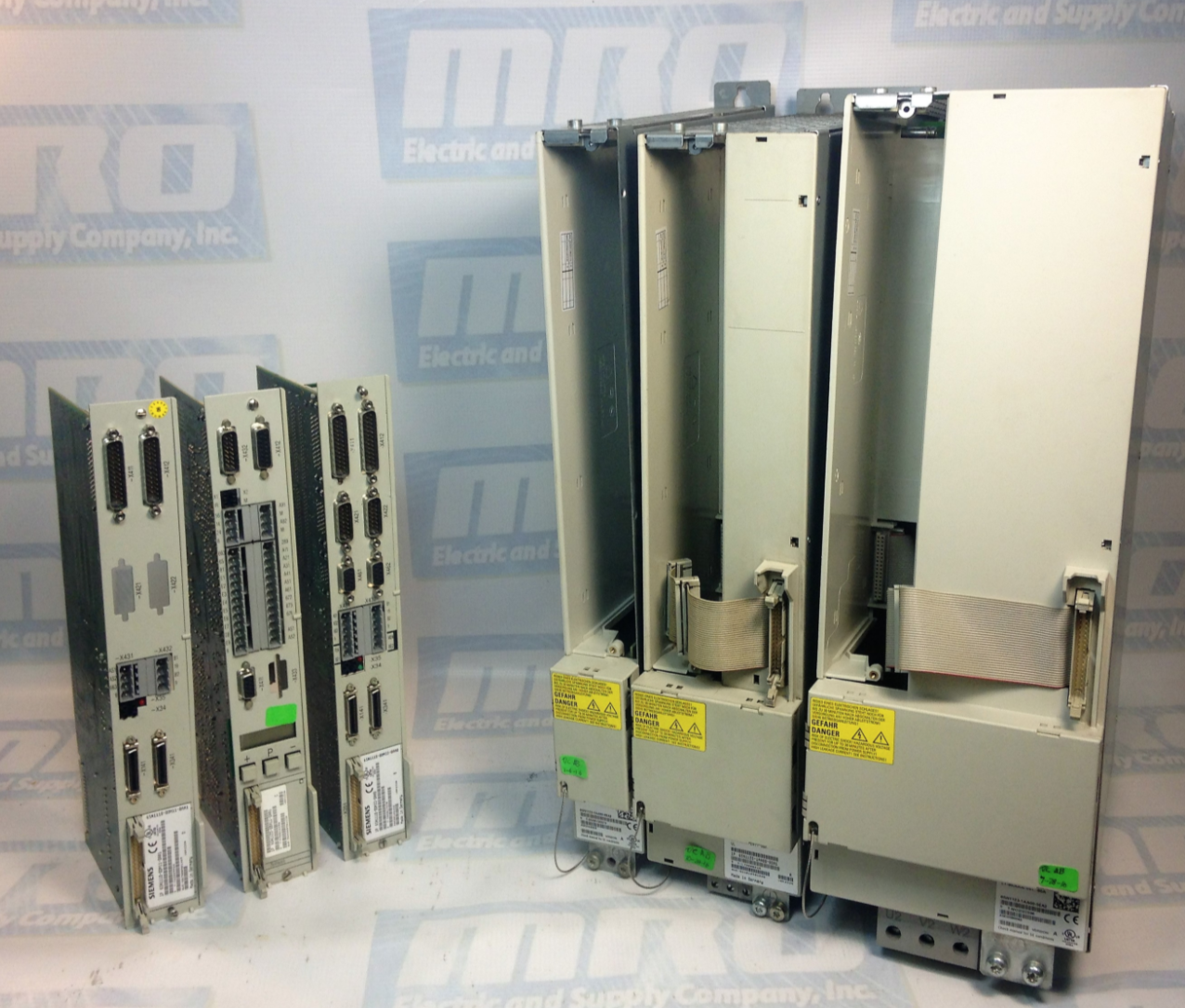
Siemens Simodrive Infeed Modules
The infeed modules are used to connect the drive group to the line supply. The infeed/regenerative feedback module (I/R module) and the module for the unregulated infeed (UI module) are used to input power into the DC link. Further, the I/R, UI, and the monitoring module also provide the electronics power supply for the connected modules. The infeed modules do not have any comprehensive overload protection. Such overload protection must be provided by the configuration and correct setting of the current values in the control boards.
For the UI module, when the motor brakes, the drive (such as the Siemens Simodrive series) energy injected into the DC link is converted into heat in the braking resistors and dissipated to the environment. These braking resistors are either integrated or mounted. When required, one or more additional pulsed resistor modules (PR modules) can be used within the limits specified when engineering the system. This module is used for the following applications:
– Machines with few or short braking cycles, low braking energy
– Drive groups with limited dynamic demands, in particular for the main spindle drive
I/R modules and HF/HFD commutating reactors form the step-up converter (7 kHz) for controlling the DC link voltage and enabling a regenerative feedback. This module is used for the following applications:
– Machines with high dynamic requirements placed on the drives
– Frequent braking cycles and high braking energy
– Control cabinet designs optimized for low operating costs
The monitoring module contains a complete electronics power supply for the equipment bus and the central monitoring functions for a separate drive group. The power is normally supplied from the 3-ph. 400 to 480 V AC line supply. For emergency retraction in case of a power failure, the power supply can also be connected to the DC link in parallel. The monitoring module is required if a higher number of drive modules in a group exceeds the electronics power supply of the infeed module (I/R or UI module). The monitoring module also allows groups of drive modules to be created in multiple cabinet compartments or tiers.
The I/R, UI, and monitoring module are located at the first module at the left in the drive group. The mounting surface for the line supply infeed and drive modules, as well as the commutating reactors and line filter, must be mounted to the mounting panels through a low-resistance connection (e.g. galvanized plates and panels). Line filters, line filter modules, and shielded cables are available in order to comply with the CE requirements regarding the radio interference voltage limit values. Shield terminal plates are available to meet EMC requirements when using shielded power cables. The overvoltage limiter module is required so that the line supply and infeed modules are implemented in conformance with UL.
In the “standby mode” of the line supply infeed, pule inhibits the power modules, terminal 63 should also be used to inhibit the pulses in the infeed. The DC link remains at the non-regulated level: this means that when the pulses are enabled, it is immediately regulated and is ready to operate. The cycle indicated above also applies to the starting frequency of the power supply (from the line supply or X181). The maximum starting frequency for the power supply is five times within a five minute period.
MRO Electric and Supply has new and refurbished Siemens parts available, including the Siemens Simodrive series. We also offer repair pricing. For more information, please call 800-691-8511 or email sales@mroelectric.com.
Updated on May 21, 2019 by Brian Hughes
