Unraveling Motor Spindle Speeds

When talking about motor spindles and CNC in industrial automation, it is natural to think that speed is the important thing to emphasize.  After all, a lot of industrial automation centers around large scale production who’s business model involves getting things made quickly.  However, speed has proven to not be the sole factor in efficient production. Varying tasks requires different speeds to complete them.  Furthermore, what speed works for one task does not necessarily work for another.

Read more: Unraveling Motor Spindle Speeds

Varying Speed Advantages

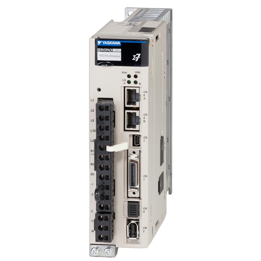
A VFD is used to control the speed of spindle motors.

Today it is very commonplace for CNC machines to run varying speeds depending on what task needs completing. Different speeds come with different advantages when dealing with motor spindles completing specific jobs. As a result, CNC machines needs to have complete variable control.

Slow Speed

In applications where precision is paramount, low motor spindle speeds are often preferred. This is particularly true in industries like aerospace and medical manufacturing, where intricate parts require meticulous machining. Low speeds also, allow for precise material removal, reducing the risk of damage to delicate components. This is crucial in applications such as milling, drilling, and engraving.

Medium Speed

Medium spindle speeds find their place in applications that require a balance between precision and efficiency. Industries like automotive manufacturing often benefit from medium-speed machining processes. These speeds are suitable for a wide range of materials and can handle various cutting tools effectively. Medium speeds are commonly employed in generic tasks like turning, threading, and grinding.

High Speed

High-speed motor spindles are the driving force behind highly productive manufacturing processes. Industries focused on mass production, such as electronics and consumer goods, rely on high-speed machining for efficiency. Rapid material removal rates and reduced cycle times make high spindle speeds ideal for tasks like milling, drilling, and routing. The ability to process materials quickly without sacrificing quality is a key advantage in these applications.

The Need for Variable Speeds

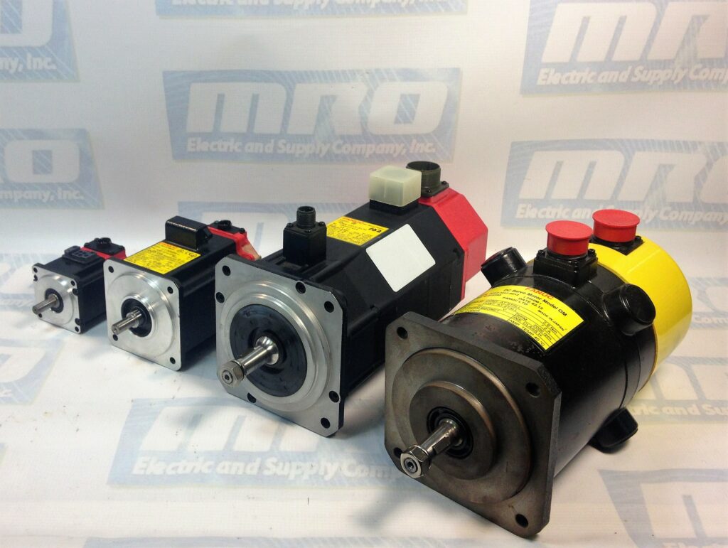
Spindle motors running at low speed are ideal for precise task, such as engraving.

Many modern CNC machines feature variable-speed motor spindles, allowing for dynamic adjustments based on specific requirements. This adaptability is particularly beneficial in environments where multiple materials or machining processes are involved. Variable speeds enable operators to optimize performance for different tasks within a single machining operation, enhancing overall efficiency and reducing setup times.

Motor spindle speeds also play a crucial role in managing heat generation during machining. In some applications, especially those involving hard materials, excessive heat can lead to tool wear and reduced tool life. Adjusting spindle speeds allows for better control over the heat generated during machining, promoting longer tool life and maintaining the integrity of the machined components.

Conclusion

In conclusion, the diverse motor spindle speeds available in industrial automation provide a spectrum of options for manufacturers to tailor their machining processes to specific needs. Understanding and effectively controlling motor spindle speeds are essential for optimizing manufacturing operations in industrial automation today. As technology advances, the integration of smart systems and real-time monitoring will further enhance the efficiency and adaptability of motor spindle speed control in industrial automation.

MRO Electric has a complete inventory of new motor spindles and VFDs. Please call 800-691-8511 or email sales@mroelectric.com for pricing and information. MRO Electric also offers repairs and replacement jobs.

Components and Functions of a CNC Machine

Since the mid-twentieth century Computer Numerical Control (CNC) machines have revolutionized the manufacturing industry. They have done so by automating and enhancing precision in the production of various components. Industries that often use them include aerospace, automotive, and electronics to create intricate and accurate parts.

Read more: Components and Functions of a CNC Machine

Function

A CNC machine is basically a sophisticated tool that translates digital instructions into precise physical movements. It allows the user to interface with

The primary functions of a CNC machine include:

  1. Digital Control: Computer programs that dictate the tool’s movements and actions. These programs contain detailed instructions for the machining process.
  2. Automated Precision: One of the key advantages of CNC machines is their ability to execute repetitive tasks with unparalleled precision. The automation eliminates the margin of error associated with manual operations, resulting in consistently high-quality products.
  3. Versatility: CNC machines can perform a wide range of tasks, from cutting and milling to drilling and engraving. Their versatility makes them indispensable in various manufacturing processes.

History

The roots of CNC technology can be found in the development of numerical control systems during the mid-twentieth century. Around this time, the aviation industry emerged as a significant catalyst for CNC innovation. Engineers sought a more efficient and precise way to machine complex components for aircraft. This led to the birth of numerical control as a solution to automate machine tools.

Early example of a CNC Machine

The 1940’s kicked off the history of the CNC machine with the introduction of punched tape systems. These systems allowed engineers to input numerical instructions into machine tools, automating certain aspects of the machining process. It wasn’t until the 1950s that the concept of CNC truly began to take shape. John T. Parsons, often regarded as the father of CNC, played a pivotal role in advancing the technology. Parsons, along with Frank L. Stulen, developed the concept of controlling machine tools through punched cards, laying the groundwork for the CNC machines we know today.

During the 1960s, the Massachusetts Institute of Technology (MIT) introduced the concept of direct numerical control (DNC). As the technology matured, industries beyond aviation started adopting CNC machines. The 1970s saw the integration of computers into CNC systems, allowing for more sophisticated programming and control. This integration, allowed the machines to become increasingly versatile and accessible. This led to widespread CNC adoption across various manufacturing sectors.

Example of modern CNC machine. Note the digitalized control panel

CNC machines evolved beyond milling to encompass a wide range of machining operations. This includes turning, grinding, and electrical discharge machining (EDM). Presently, CNC machines are at the forefront of advanced manufacturing, shaping industries ranging from automotive and aerospace to electronics and healthcare.

Parts

While there are varying models and designs, CNC machines generally are made of several different parts. These parts are crucial to the function of the CNC.

  1. Control Unit:
    • Computer: The brain of the CNC machine, the computer processes the instructions from the program and translates them into electrical signals.
    • Control Panel: Operators use the control panel to input data, set parameters, and monitor the machine’s performance.
  2. Drive System:
    • Motors: Drives the movement of the cutting tool along the specified path. Common types include stepper motors and servo motors.
    • Ball Screws/Rack and Pinion: These components convert the rotational motion of the motors into linear motion, guiding the tool precisely along the desired path.
  3. Tooling System:
    • Cutting Tool: The cutting tool is an essential component that physically shapes the material. Different tools are used for various machining operations.
    • Tool Changer: In machining processes that require multiple tools, a tool changer automates the process of switching between tools.
  4. Work Holding Device:
    • Vise or Chuck: The workholding device secures the raw material in place during machining. It ensures stability and accuracy throughout the cutting process.
  5. Coolant System:
    • Coolant Tank and Pump: Machining generates heat, and a coolant system helps dissipate this heat, preventing damage to the tool and workpiece. It also aids in chip removal.
  6. Axis System:
    • Linear Guides: These guides facilitate the smooth movement of the machine’s axes. They play a crucial role in maintaining accuracy during machining.
    • Axis Motors: CNC machines typically operate in three or more axes (X, Y, Z), and each axis has its motor for precise control.

Conclusion

Understanding the functions and components of a CNC machine is essential for those involved in the design and operation of these advanced manufacturing tools. As technology continues to advance, CNC machines are likely to play an even more pivotal role in shaping the future of manufacturing processes.

Troubleshooting Schneider Electric Magelis HMIs

Human Machine Interfaces (HMIs) play a crucial role in modern industrial automation, allowing operators to monitor and control various processes. Schneider Electric’s Magelis HMIs are renowned for their reliability and performance. However, like any technology, they can encounter issues that require troubleshooting. In this comprehensive guide, we will explore common problems with Schneider Electric Magelis HMIs and provide step-by-step solutions to help you keep your operations running smoothly.

Schneider Electric XBTGT5330

Understanding Schneider Electric Magelis HMIs

Before diving into troubleshooting, it’s essential to have a basic understanding of Schneider Electric Magelis HMIs. These devices are used in a wide range of industries, including manufacturing, energy, and infrastructure. They provide an intuitive interface for operators to interact with machines, view real-time data, and make informed decisions.

Magelis HMIs come in various models and sizes, from compact panels to advanced touchscreens. They are known for their robustness, high-quality displays, and compatibility with Schneider Electric’s automation solutions. However, even the best HMIs can face issues, and knowing how to troubleshoot them can save time and resources.

Common Schneider Electric Magelis HMI Issues

1. HMI Display Problems

Symptom:

  • Blank or distorted screen.
  • Touchscreen not responding.
  • Flickering or frozen display.

Solution:

  1. Check Power Supply: Ensure the HMI is receiving adequate power. Verify connections to the power source and power supply unit.
  2. Screen Calibration: If the touchscreen is unresponsive or inaccurate, recalibrate it following the manufacturer’s instructions.
  3. Graphics Driver: Update the graphics driver to the latest version compatible with your HMI model.
  4. Hardware Issues: Inspect the HMI for physical damage or loose connections. Replace damaged components if necessary.

2. Communication Problems

Symptom:

  • HMI unable to communicate with PLC or other devices.
  • Error messages related to communication.

Solution:

  1. Check Cables and Connections: Verify that all cables and connections between the HMI and other devices (PLC, sensors, etc.) are secure and undamaged.
  2. Communication Settings: Ensure that the communication settings (baud rate, protocol, IP addresses) on the HMI match those of the connected devices.
  3. Firewall and Security: Disable or adjust firewall settings on networked devices to allow communication.
  4. Network Troubleshooting: If using a networked HMI, diagnose network issues such as IP conflicts or network congestion.

3. Software and Programming Errors

Symptom:

  • Unexpected program crashes or errors.
  • Incorrect data displayed on the HMI.

Solution:

  1. Software Updates: Make sure you are using the latest version of the HMI software. Update if necessary.
  2. Check Logic and Scripting: Review and debug the logic and scripts used in your HMI application. Ensure they are error-free.
  3. Backup and Restore: Regularly backup your HMI project. If issues arise, you can restore from a known-good backup.
  4. Memory Management: Check available memory on the HMI. Clear unnecessary files and logs that might be consuming resources.

4. Hardware Failures

Symptom:

  • HMI hardware components (buttons, LEDs, etc.) not functioning correctly.
  • Unusual noises or smells from the HMI.

Solution:

  1. Component Replacement: If specific hardware components are malfunctioning, replace them with compatible parts.
  2. Overheating: Check for overheating issues by ensuring proper ventilation. Clean any dust or debris that might be blocking airflow.
  3. Inspect Internal Components: If comfortable with electronics, open the HMI enclosure (if applicable) and inspect internal components for damage or loose connections.

5. Security Concerns

Symptom:

  • Unauthorized access to the HMI.
  • Concerns about cybersecurity threats.

Solution:

  1. Password Protection: Ensure that your HMI is password-protected. Change default passwords and enforce strong password policies.
  2. Firewall and Security Measures: Implement firewalls, access control lists, and other security measures to protect your HMI from external threats.
  3. Regular Updates: Keep the HMI software and firmware up to date to patch security vulnerabilities.
Schneider Electric HMIGTO5310 HMI

Advanced Troubleshooting Techniques

For more complex issues that cannot be resolved using the above solutions, consider these advanced troubleshooting techniques:

  1. Log Analysis: Examine system logs and error messages to identify the root cause of the problem.
  2. Factory Reset: As a last resort, perform a factory reset of the HMI, but only after backing up essential data.
  3. Technical Support: Contact Schneider Electric’s technical support or consult their knowledge base for assistance with specific issues.
  4. Hardware Diagnostics: Use diagnostic tools and equipment to test the HMI’s hardware components thoroughly.

Preventive Maintenance

Preventing issues is as important as troubleshooting them. Here are some preventive maintenance tips for Schneider Electric Magelis HMIs:

  1. Regularly clean the touchscreen and enclosure to prevent dust and dirt buildup.
  2. Monitor system logs and performance regularly to catch issues before they become critical.
  3. Update software and firmware as recommended by Schneider Electric.
  4. Train operators and maintenance personnel on proper HMI usage and basic troubleshooting.

Conclusion

Schneider Electric Magelis HMIs are vital components in industrial automation and keeping them in optimal condition is crucial for efficient operations. With the troubleshooting techniques and preventive maintenance tips outlined in this guide, you’ll be better equipped to address common HMI issues and ensure the continued success of your automation processes. Remember, when in doubt, consult Schneider Electric’s technical support for expert assistance.

Surge Protectors Vs Power Strips

In a world full of misinformation and misconception, people tend to overlook one bit of knowledge. This specific misinformation manifests in the form of two specific objects, commonly found at home and at work. These objects hide under your bed. They lie forgotten about in the crevice behind your office desk. Heck! You may even find two to three of them daisy-chained together by some rabbel-rouser rebelling against OSHA!

Of course, I am talking about power strip and surge protectors. At a glance they both look and function in a similar way. However, once you get the past the surface level similarities, the differences begin to reveal themselves. At this point the importance of knowing the difference becomes very clear.

Read more: Surge Protectors Vs Power Strips

History

Power Strip

The history of the power strip traces back to the early 20th century. The increase demand for electricity in homes and workplaces made it necessary to have a way to power more devices. The earliest patent for a power strip dates back to 1929. As more electronic devices and appliances became integral to daily life, the need for additional electrical outlets became apparent. The earliest power strips were simple extensions of existing electrical wiring. They offered a convenient way to power multiple devices from a single wall outlet. These early versions were rudimentary, often lacking safety features and surge protection.

Advancements in electrical engineering led to the integration of safety features. These included circuit breakers and individual switches for each outlet. The 1970s saw the update and release of the power strip type that we all know today. With the rise of computers, home entertainment systems, and an increasing number of electronic gadgets, power strips became ubiquitous in households and offices. They played a pivotal role in managing the complex web of cords. They also provided a centralized power source for various devices. Power strips continue to evolve, incorporating smart technologies and energy-efficient designs.

Surge Protector

As more sensitive electronic equipment like computers and televisions became commonplace, the vulnerability of these devices became evident. Surge protectors emerged as a response to this challenge, aiming to mitigate the risks associated with power fluctuations. Early surge protectors were rudimentary. They often utilized devices like metal oxide varistors (MOVs) to redirect excess voltage away from connected devices. However, these early models lacked the sophistication and comprehensive protection features seen in modern surge protectors.

As technology advanced and electronic devices became more intricate and expensive, surge protectors evolved to offer enhanced protective mechanisms. Throughout the latter half of the 20th century and into the 21st century, surge protectors integrated advanced technologies, such as transient voltage suppressors and thermal fuses, to provide more robust defense against power surges. The growing awareness of the importance of surge protection has led to the widespread adoption of surge protectors in homes, offices, and industrial settings. Today’s surge protectors not only shield devices from voltage spikes. They also often include additional features like USB ports and smart functionalities to meet the diverse needs of contemporary users.

So What’s the Difference?

As mentioned above, at an initial glance power strips and surge protectors may seem like interchangeable jargon for the same item. However, the difference between them lies in their functionality and purpose. Power strips function as a tool for allowing power to multiple devices at once. The modern conception used today comprises of a multi-outlet strip with a power switch installed. Power strips serve multitude of uses across various industries. Shops utilize them for being able to use multiple power tools at the same time. Offices use them to hook multiple computer components. In the home they are often found in the living room powering the entire family entertainment system.

While the surge protector essentially finds itself used in the same way that the power strip does. Unlike the power strip, the surge protector has the added bonus of being able to actually protect devices if there is a voltage spike. Often these spikes (more commonly referred to as surges) come from things lightning strikes or power outages. It is often advised that all expensive and sensitive devices be connected to a surge protector as to ensure their longevity.

Conclusion

Understanding the disparity between power strips and surge protectors is vital for making informed decisions about the safety of your electronic devices. While power strips offer convenience, surge protectors provide essential protection against unexpected voltage fluctuations, ensuring the longevity and functionality of your valuable electronics. Finally, if you are trying to buy a surge protector make sure to read the box fully to ensure you are not buying a power strip.

Siemens SINAMICS Drives: Powering Precision and Efficiency in Industrial Automation

In today’s rapidly evolving industrial landscape, efficiency, precision, and adaptability are paramount. Siemens SINAMICS drives have emerged as a cornerstone technology, playing a pivotal role in ensuring that manufacturing and automation processes run seamlessly. These drives, engineered by Siemens, a global leader in industrial automation, bring sophistication and versatility to motor control systems. In this comprehensive post, we will delve into the world of Siemens SINAMICS drives, exploring their features, applications, benefits, and why they are the preferred choice in various industries.

Siemens Sinamics 6SL3120-1TE13-0AD0

Table of Contents:

  1. Understanding Siemens SINAMICS Drives
    • Introduction to SINAMICS Drives
    • Key Components
    • Variants and Models
  2. Applications Across Industries
    • Manufacturing and Robotics
    • Energy and Utilities
    • Automotive Industry
    • Materials Handling
    • More Beyond the Horizon
  3. Advanced Features of SINAMICS Drives
    • Seamless Integration
    • Precise Control and Feedback
    • Energy Efficiency
    • Safety and Reliability
  4. Benefits of Utilizing Siemens SINAMICS Drives
    • Increased Productivity
    • Reduced Energy Consumption
    • Enhanced Process Control
    • Maintenance and Cost Savings
  5. SINAMICS Drives in Action: Real-World Success Stories
    • Case Study 1: Automotive Manufacturing
    • Case Study 2: Renewable Energy
    • Case Study 3: Food and Beverage Industry
  6. Future Trends and Innovations
    • Digital Twins and Predictive Maintenance
    • IoT Integration
    • Sustainability Initiatives
  7. Conclusion: Powering the Future of Industrial Automation
Read More

High Medium Low Voltage

Understanding low, medium, and high voltage is considered to be crucial knowledge in industrial automation.  Not only does this knowledge facilitate a safer environment, but also promotes efficiency and functionality within the working systems.  Here is a breakdown that covers the differences in voltages, the safety aspect, and how knowing about them proves important in the field of industrial automation.

Read more: High Medium Low Voltage

What is Voltage?

Voltage refers to the force that moves electric charges through a conductor. It’s a fundamental aspect of electrical systems, crucial for powering devices and transmitting electricity across various distances. Industries categorize voltage levels into high, medium, and low based on their magnitude and the applications they serve.

  • Low Voltage (LV): Up to 1,000V
  • Medium Voltage (MV): 1,000V to 35,000V
  • High Voltage (HV): Above 35,000V

Low voltage is commonly used in residential and commercial settings, while medium voltage is used in power distribution systems, and high voltage is essential for transmitting electricity over long distances.

Low Voltage

Generally, low voltage refers to voltages below 1000 volts (V). Common examples include household outlets in many countries operating at 120V or 230V. Additionally, low-voltage systems might involve voltages as low as 12V or 24V used in electronics, small appliances, and LED lighting.  

Low-voltage systems are prevalent in everyday devices and smaller-scale electrical applications. They power household electronics, chargers, small motors, and many portable devices. Low voltage remains relatively safe for direct human contact. Furthermore, it remains widely used in residential, commercial, and industrial settings due to its lower risk of electrical hazards.

While low voltage is generally safer to handle, improper handling or faulty wiring can still pose risks of electrical shock or fire hazards, necessitating proper installation and adherence to safety standards.

Medium Voltage

Medium voltage typically ranges from 1000 volts to 35,000 volts. This level of voltage is commonly used in industrial settings, power distribution systems, and larger facilities.

It plays a crucial role in power distribution. They transport electricity from power stations to transformers, which then step down the voltage for use in commercial and residential areas. Medium voltage powers heavy machinery, large motors, and equipment in industries, hospitals, data centers, and universities.

Medium-voltage systems require specialized equipment and trained personnel for installation, maintenance, and operation due to increased risks of electrical accidents. Safety protocols, protective gear, and comprehensive training are essential for handling and working with medium-voltage systems.

High Voltage

High voltage refers to voltages exceeding 35,000 volts and can extend to extremely high levels used in power transmission lines, reaching hundreds of kilovolts (kV) or even megavolts (MV) in some cases.

High-voltage systems primarily serve the transmission of electricity over long distances. Power generated at plants is stepped up to very high voltages for efficient transmission across power lines. High-voltage systems are crucial for delivering electricity from power plants to substations, where it is then stepped down to medium or low voltage for distribution to end-users.

Working with high-voltage systems requires rigorous safety measures, specialized equipment, and highly trained personnel. The risks associated with high-voltage systems are significantly higher, including severe electrical shock, arc flashes, and other potentially fatal accidents.

Reasons to Know the Difference

Workplace Safety

In industrial or commercial settings, where medium or high voltage systems are common, employees must be well-versed in safety protocols specific to each voltage level. Proper training, understanding of safety procedures, and equipment usage reduce the risk of accidents, ensuring a safer work environment

.

Efficiency and Integrity

Each voltage level serves specific purposes within an electrical system. Low voltage is suitable for smaller-scale applications, while medium voltage is crucial for efficient power distribution across larger areas. High voltage is indispensable for long-distance power transmission. Understanding these distinctions ensures that the right voltage is used for the intended application, optimizing efficiency.

Mismatching voltage levels or using incorrect equipment can compromise the integrity of electrical systems. Understanding the correct voltage requirements helps prevent equipment damage, system failures, and electrical fires, ensuring the longevity and reliability of the electrical infrastructure.

Compliance and Standards

Proficiency in handling different voltage levels is often a prerequisite for certifications and licensing in electrical work. Electricians, engineers, and technicians must demonstrate knowledge and competence in dealing with specific voltage levels to obtain the necessary credentials.

Emergencies

During emergencies such as electrical faults, fires, or accidents involving electrical systems, responders need to quickly identify and manage the voltage level involved. Knowledge about the voltage level enables them to take appropriate actions to mitigate risks and ensure a safe resolution of the situation.

Conclusion

In essence, knowledge of the differences between high, medium, and low voltage levels is foundational for maintaining safety, ensuring efficiency, complying with regulations, and responding to emergencies. It stands as the pinnacle standard for safe and efficient utilization of electrical power across various domains. This ranges from everyday household electronics to large-scale industrial infrastructure.

Troubleshooting Fanuc Power Supplies: A Comprehensive Guide

Power supplies are the lifeblood of any industrial automation system, and Fanuc power supplies are no exception. These critical components ensure that your machines receive a stable and reliable source of electrical power, enabling them to function efficiently and accurately. However, like any other electronic equipment, Fanuc power supplies can encounter issues that disrupt production and lead to costly downtime. In this comprehensive guide, we will delve into the world of troubleshooting Fanuc power supplies, equipping you with the knowledge and tools to identify and resolve common problems effectively.

Fanuc A06B-6140-H015 Power Supply

Understanding Fanuc Power Supplies

Before we dive into troubleshooting, it’s crucial to have a basic understanding of Fanuc power supplies. These units are responsible for converting the incoming electrical power (typically AC voltage) into the required DC voltage to operate various components within a CNC (Computer Numerical Control) system. They play a pivotal role in ensuring that the control system, servomotors, and other machine components receive the right voltage and current for smooth operation.

Common Issues with Fanuc Power Supplies

Fanuc power supplies are robust and reliable, but they can still experience problems over time. Here are some common issues you might encounter:

  1. No Power Output: The power supply fails to provide any output voltage, resulting in a complete machine shutdown.
  2. Voltage Fluctuations: The output voltage fluctuates, leading to erratic machine behavior and potential damage to sensitive components.
  3. Overheating: Excessive heat generation within the power supply can lead to thermal shutdowns or even permanent damage.
  4. Fuse Blown: Frequent blowing of fuses can indicate a problem within the power supply or an overload in the connected equipment.
  5. Noise and Interference: Poorly filtered power supplies can introduce electrical noise into the system, causing erratic operation or sensor errors.
  6. Inadequate Output: The power supply might not provide enough current for the connected devices, leading to operational issues.
Read More