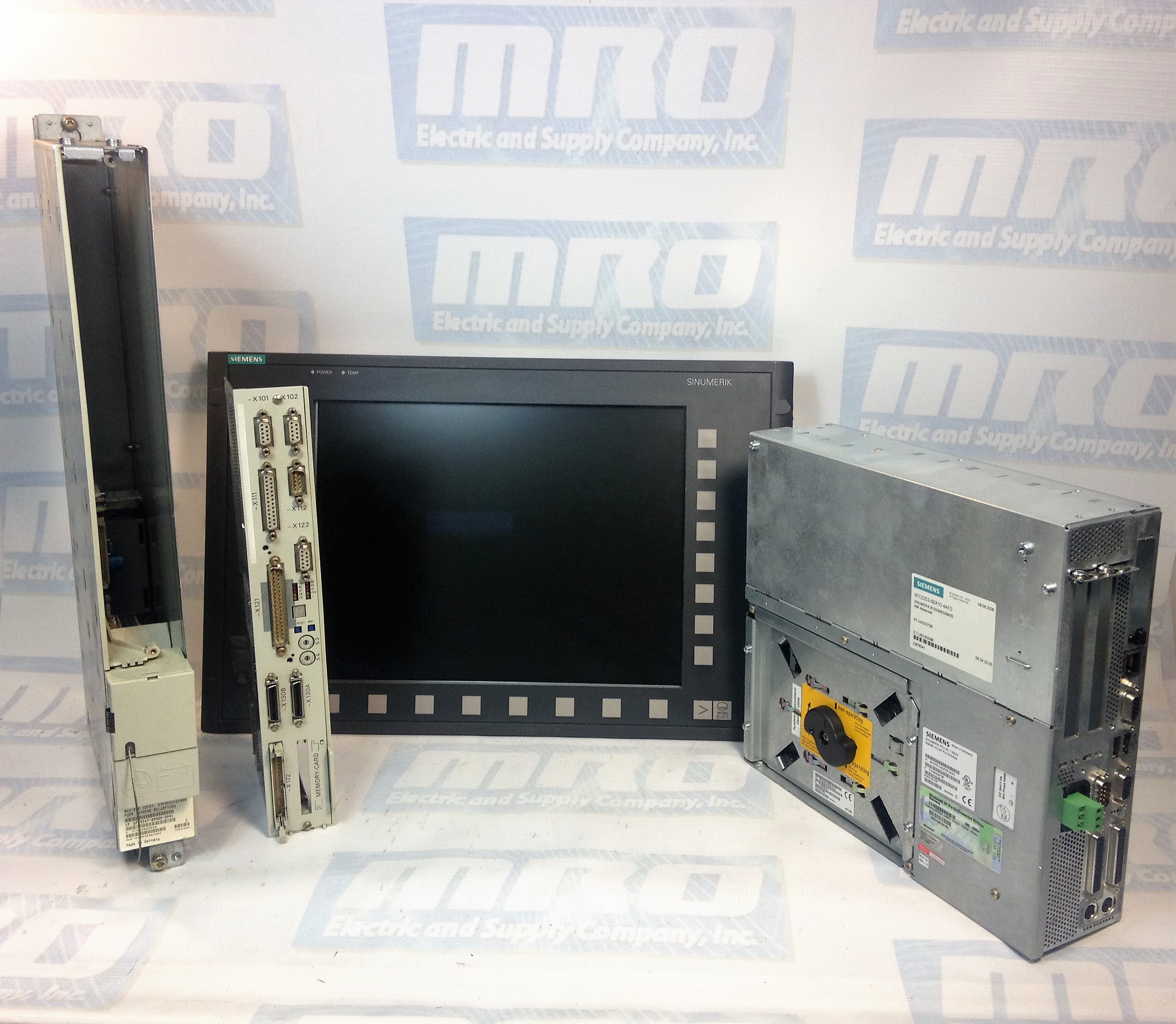
FANUC CNC machine is an extremely useful tool – but like many tools, it’s susceptible to breaking. Read on to learn common FANUC issues and how to best troubleshoot to solve the problem.
What is the proper method to test a motor for a short?
The proper way to troubleshoot a FANUC motor for a short is to first lock out the machine, remove the cable from the drive, and test all three motor phases to ground with a megohmmeter. This will test both the motor and the cable for problems.
Why am I getting errors when I connect to my FANUC drive’s RS-232 port?
There are a number of explanations for these errors. The RS-323 port is a high-fail component on a FANUC drive as it is very susceptible to electrical surges. However, the RS-232 cable is also another high-fail item. Ensure that you are using a cable that is known to be functional when communicating. Otherwise when you attempt to read-in or punch-out a cable, you will get an 086 alarm that is going to indicate that the cable is incorrect, or that the port has failed.
To test whether the cable or the port has failed, take a known good cable and insert it into the RS-232 port. Next, set your machine up to receive a file. The screen should being to flash “READ”. Next, transmit your file into the machine tool. If the machine continues to flash “READ” (or “LSK” on modern controls) but never receives the file, you have a defective communications port on either the memory board or the master board. These boards or your machine will need to be sent in for repair.
What is an Axis Communications Error?
An Axis Communications Error indicates a communications problem between the motor encoder and the CNC control. This can be caused by the motor encoder itself, the cable going to the encoder, or the axis control card the cable is plugged into.
What is an Excess Error Alarm and why is it caused?
Generally, an Excess Error means that the machine has moved beyond its allowable tolerance. The CNC has told the FANUC servo drive to make a move, the servo drive moves the motor, which in turn moves the encoder. As the machine moves, there will be some deviation. This deviation is known as the Excess. The parameters set how much deviation/excess should be allowed.
These errors can be caused by a variety of problems. For example, a dull tool can caused the axis to be pushed out of position which results in a deviation error. Debris build up can cause deviations while the machine is stopped. Additionally, a failed servo drive can also cause deviation errors.
What is FANUC 401 Servo Alarm?
Alarm 401 is a very generic FANUC alarm. It simply means that the servo’s did not obey. The CNC, which is in charge of the servos, tells the servo drives to turn on and remain on. If for whatever reason the servo drive turns itself off without the permission from the CNC, the CNC will generate a 401 alarm. This alarm will usually occur with other alarms, such as the 414 Alarm.
What is FANUC Servo Alarm 414?
The FANUC Servo Alarm 414 is an alarm issued by the CNC that says a problem has been found in either the servo drive or the feedback system. The alarm will show which axis is causing the problem. To identify the specifics of this alarm, you must go into the CNC diagnostics page. Diagnostics number 200 on the 16th row will indicate what is causing the problem.
What is the difference between a High-Current Alarm and an Over-Current alarm?
A high current is an abnormal current that can be caused by noise. When the system detects this, it will generally shut the machine down and generate a High-Current Alarm. This FANUC alarm code is usually caused by defective servo drive or cooling contamination inside of the motor windings or cable.
An Over-Current Alarm indicates that too much current has flowed through the DC link. This is usually caused by a short in the system, an unplanned contact, a defective transistor module, or dull tooling attempting to make a cut.
Why do I get a Soft Overtravel Alarm when I try to reference a newly installed motor?
When the CNC power down, it remembers its last known position. When you restart the machine, an incremental encoder will ask that the machine be re-positioned. When you try to do a re-reference of the machine tool, and it doesn’t agree with where the last known position was, the machine with automatically go into a default that indicates a Soft Overtravel Alarm. These alarms can occur as any point in the travel of the machine. To bypass this alarm, power the machine down and hold down the key with the letter “P” on it as well as the “Cancel” button (at the same time). Then power the machine up while you continue to hold down both of these buttons. If you do this, the machine will ignore all Soft Overtravels until the first zero referenced position has been done on that axis, and will clear the Soft Overtravel Alarms.
I unplugged my AC or DC FANUC motors, and now I am getting a 300APC Alarm. What is that?
A 300APC Alarm indicates that you are using an absolute pulse coder. The difference between an absolute pulse coder and a incremental pulse coder deals in the memory retention of the position. Using a CNC control with an incremental pulse coder, you must reference the machine every time you turn the machine back on.
With an absolute pulse coder, there is a battery backed memory that retains the position of the machine tool when it powers down. When the CNC machine turns back on, it asks the encoder its position, and the encoder then responds back with its current position. If it is within tolerance of where it was when it shut down, the CNC will continue to run the program. However, if you lose the memory retention due to an encoder cable being unplugged, you will end up with the 300 level APC alarms. These FANUC alarms simply signify that the machine must be re-referenced. The re-referencing procedure is determined by the machine tool builder – consult your machine tool builder manual for the proper operation.
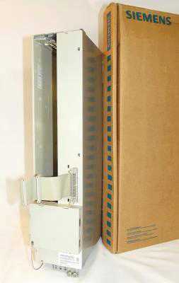
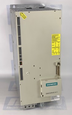
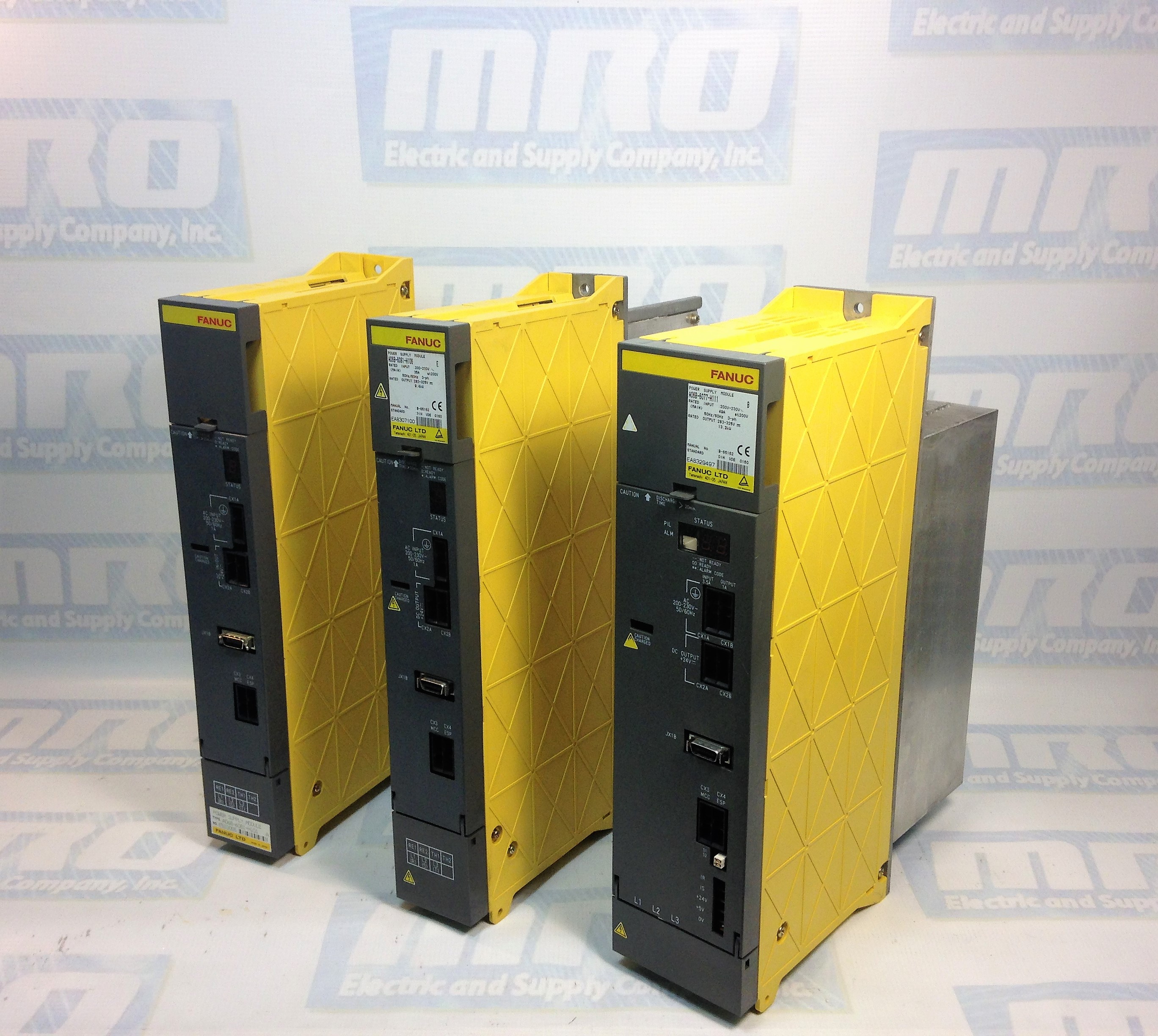
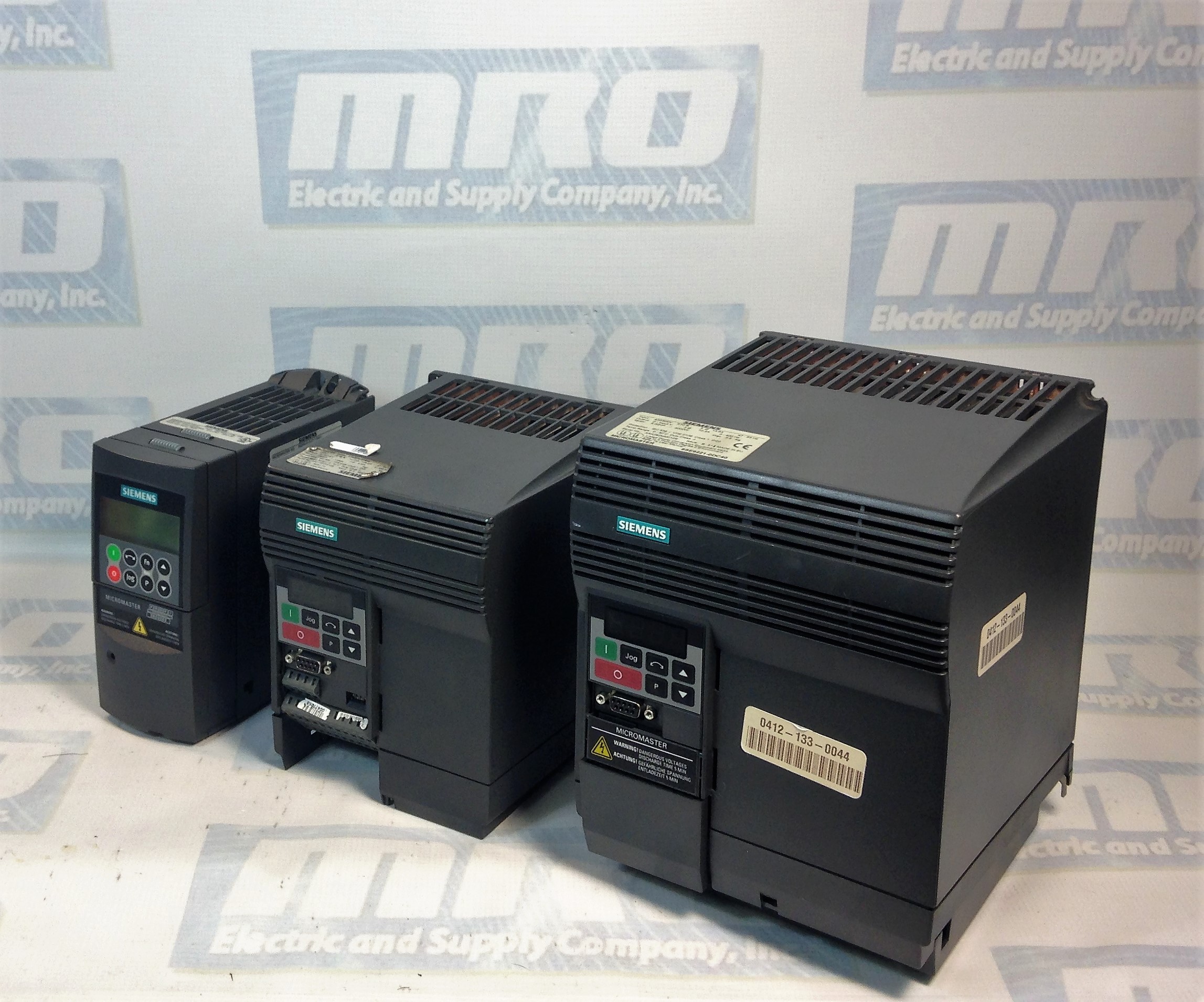
If this FANUC troubleshooting manual was not comprehensive enough, MRO Electric stocks new and refurbished FANUC products, and also offers reliable FANUC repairs. Please call 800691-8511 or email sales@mroelectric.com for a quote.