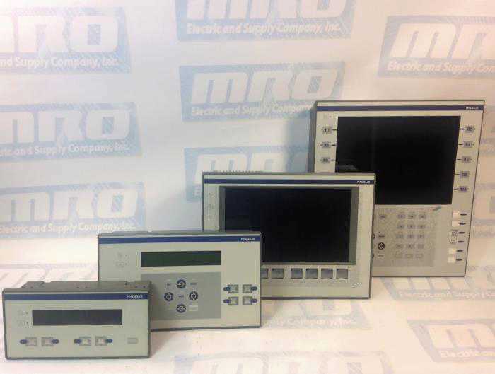
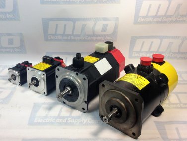
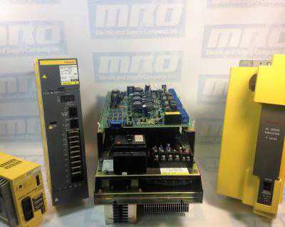
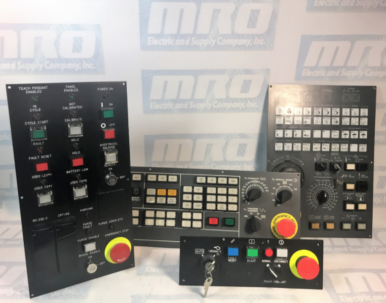
Programmable logic controllers, also known as PLCs, initially came about in the late 1960s. PLCs were designed to replace relay-based machine control systems in the major U.S. vehicle manufacturing space. The relay-based control systems were considered hard to use and were disliked amongst those in the automation and manufacturing in.
In 1968, Dick Morley of Bedford Associates in Massachusetts designed the Modular Digital Controller, later dubbed the Modicon. After the Modicon 084’s initiation into the world, there was no looking back to those relay-based control systems. Be sure to check out our article covering Modicon PLC history to learn more.
PLCs are user-friendly microprocessor-based specialty computers that carry out control functions, many of which are of high levels of complexity. They are engineered to endure harsh and strenuous situations such as in heated, cooled and even moist environments. Used for automation usually in the industrial electromechanical space, PLCs are computers that deal with the controlling of machinery, often on the following:
- factory assembly lines
- power stations
- distribution systems
- power generation systems
- gas turbines
PLCs are programmed using a computer language. Written on a computer, the program is then downloaded to the PLC via a cable. These programs are stored in the PLCs memory. The hard-wired logic is exchanged for the program fed by its user during the transition between relay controls to PLC. The manufacturing and process control industries have gotten to take advantage of PLC applications-oriented software since Modicon PLCs inception.
PLC Functions and Directions
PLCs use programmable memory in order to store particular functions and directions. Some functions and directions would include:
- on control
- off control
- timing
- sequencing
- counting
- arithmetic
- data manipulation
PLC Types
Understanding the different types of PLCs will be very helpful when looking into PLC security.
The numerous types of PLCs can be organized into three principal categories:
- Advanced PLC: Advanced PLCs offer the greatest processing power out of all of the PLC types. They feature a larger memory capacity, higher input/output (I/O) expandability, and greater networking options.
- Compact Controller: Logic Controllers are increased intermediate level offerings with an increased set of instructions and a greater input/output (I/O) than a run-of-the-mill logic controller
- Logic Controler: A logic controller is often referred to as a ‘smart relay’. They are generally straightforward to use and considered a good place to begin when becoming acquainted with PLCs. They are cost-effective for low input/output (I/O), slower speed applications.
PLC Security
As security concerns remain in many professional spaces including the factory automation space, becoming up-to-speed with the different types of PLC Security is imperative. By creating and implementing an effective strategy to remain secure, you will likely avoid issues, downtime, and setbacks. Understanding the different types of PLCs will be very helpful when looking into PLC security.
PLC Cybersecurity: How the control network is linked to the internet, as well as other networks. A handful of PLC issues could likely involve the following:
- Incident response planning and plans;
- Issues drafting and reviewing policies
- Issues drafting and reviewing procedures
- Retention of cybersecurity experts and vendors;
- A need for preparation of a breach:
- exercises
- training
- breach simulations
- A need for cybersecurity insurance review and counseling
- A demand for record management and information infrastructure;
- Privacy risk management
- Assessment of cybersecurity risk in mergers and acquisitions;
- Payment Credit Industry (PCI) Compliance protocols
- Vendor contract management protocols
- Supply chain risk management
PLC Physical Security: Although PLC physical security differs from PLC cybersecurity, it is still important and should be prioritized when an individual or a company is undergoing breach simulations, training, and exercises. PLC physical security deals with:
- correcting default passwords
- ensuring only certified individuals are in the control system’s environment
- limiting access to thumb drives and securing access
MRO Electric and Supply maintains a comprehensive stock of Modicon PLC parts, including the Modicon Quantum series. Also, feel free to check out our repair and core exchange programs to learn how to save.
Understanding Issues with Security
As many in the automation space may know, PLC cybersecurity wasn’t a thing a decade ago. These days, PLCs are connected to business systems through any run-of-the-mill network and aren’t separated from other networks that other automation equipment may also be on. As time goes on, it’s becoming more and more common to see TCP/IP networking from a business system standpoint. By connecting via TCP/IP, data exchange, as well as more rational and scalable business decisions, is enabled.
PLC Security Factors:
- Although it may not actually connect to the internet, a control system is unsafe. Contrary to popular belief, a modem connection could also experience intrusion and a hack.
- Wireless networks, laptop computers, and trusted vendor connections could be other sources of connections in which people may be likely to overlook.
- Keep in mind that the majority of IT departments are unaware of factory automation equipment, including CNCs, CPUs, PCBs, robotics parts and, last but not least, PLCs.
- Piggybacking off of the last point, IT departments’ lack of experience with the aforementioned equipment, along with their lack of experience with industrial standards and scalable processes indicate that they should not be in-charge and responsible for a company’s PLC security. Nobody wants an annoyed employee to make inappropriate changes to a PLC’s communication highway.
- Hackers do not necessarily need to understand PLC or SCADA to block PC-to-PLC communication. They absolutely do not need to understand a PLC or SCADA system to cause operational or programming issues.
- Often times, control systems, including ones that many PLCs integrate with, use Microsoft Windows, which is very popular amongst hackers.
- Some PLCs crash simply by pinging an IP address, like what happened at the Brown’s Ferry Nuclear Plant, which is located in upstate Alabama. Since the incident in 2006, the plant has undergone numerous security, operational, and management improvements.
In conclusion, when a security breach occurs, regardless of the specifics, understanding that time is of the essence will help smooth over most incidents. Trusting who has access to a control systems environment and thumb drive is crucial. If someone has access to the control system environment and thumb drive, ensure they’re well-qualified and up-to-speed with their team and/or company.
