FANUC A16B-1212-0100 Power Supply Unit

MRO Electric and Supply has new and refurbished FANUC A16B-1212-0100 power supply units available now, and also offers repair pricing. For more information, please call 800-691-8511 or email sales@mroelectric.com.
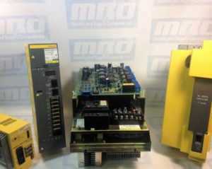
a16b-1212-0100 wiring diagram
A16B-1212-0100 Wiring Diagram

The A16B-1212-0100 is an easy to mount CNC power supply that is designed to connect directly to the System 0 master PCB. All its AC inputs and DC outputs are linked via connectors. Because the power supply unit has a built-in input unit function, it is not necessary to prepare a a separate relay or input unit for switching the AC input on and off. The AC input can be connected directly to the power supply unit. The unit has an AC service outlet, which is switched on and off simultaneously with the power supply unit. This AC service outlet can be used to supply power to a unit such as a fan motor. Sometimes the alternate FANUC part number P007P0355 is used.

FANUC A16B-1212-0100 Input / Output Connectors

Connector NameDescription
CP1200/220/230/240 VAC input
CP2200/220/230/240 VAC output
(switched on and off simultaneously with the power supply unit)
CP3- Power on/off switch contact signal input.
- External alarm signal input.
- Alarm signal input.
CP12- Supply of +5 V, +15 V, –15 V, +24 V, and +24E to the master
printed–circuit board.
- EN signal output.
CP14- +24E supply for the additional I/O B2 printed circuit board
(for Series 0).
- +24E supply for the connection unit (for Series 15)
CP15+24V supply for the 9” monochrome CRT/MDI unit (for Series 0).

* MRO Electric can offer replacement 9" monitors for your unit.

Descriptions of the A16B-1212-0100 I/O Signals and Display LEDs
    1. AC power supply display LED (green) – When an AC power source is connected to the power supply unit, the LED lights regardless of whether the unit is on or off.
    1. Alarm display LED (red) – If the power supply unit is switched off because of an alarm condition due to a failure such as an output error, the alarm display LED lights and remains on until the alarm condition is cleared by pressing the OFF switch or shutting down the AC power supply.
  1. ENABLE signal EN (output) – This TTL level signal indicates that all DC outputs are normal. It becomes low if an output failure is detected in any circuit.
  2. Power supply on/off control signal ON–OFF–COM (input) – If two switches are connected to this circuit as shown below, pressing the ON switch turns on the power supply unit, while pressing the OFF switch turns the unit off. If an alarm occurs in the power supply unit, and the alarm display LED lights in red, however, pressing the ON switch will not turn on the power supply unit. In this case, it is necessary to remove the cause of the alarm and press the OFF switch. Pressing the OFF switch clears the alarm condition. Subsequently pressing the ON switch turns on the power supply
    unit.
  3. External alarm signal AL (input) – When a contact signal from another unit or external power supply becomes ”closed,” the ENABLE signal of this power supply unit becomes low, thus immediately turning off the power supply unit.
  4. Alarm signal FA–FB (output) –  This contact signal indicates the state of all DC outputs. The contact is open when all the DC outputs are normal. It is closed if an output failure is detected in any DC output circuit. If an external alarm signal (item 5) is connected, the FA–FB contact opens, when all DC outputs are normal and the external alarm signal is ”open.” The contact closes when the external alarm signal becomes ”closed.”
Adjustments and Settings

The FANUC A16B-1212-0100 power supply unit requires no adjustment or setting. Do not attempt to adjust the reference voltage (=10.00V) at A10 unless absolutely necessary, because the reference voltage has been adjusted during unit test; merely confirm the voltage across A10 and A0 of check connector CP16. If the reference voltage at A10 falls outside the rated range, set it to 10.00V, using VR11, while measuring the voltage with a digital voltmeter. Rotating VR11 clockwise increases the voltage at A10. After the power supply unit is replaced, always to check the reference voltage at A10.

a16b-1212-0100
A16B-1212-0100
fanuc repair

Automation Cleanup Procedures for Flood Damages in TX & LA

Automation Cleanup Procedures for Flood Damages in TX & LA

MRO Electric is determined to provide the best service and support to businesses affected by Hurricane Harvey during these difficult times as they resume operation and employees get back to work.

Water-immersed electronic devices and motors in automation systems need appropriate treatment after flood water subsides. We have compiled information we learned from our past flood relief activities below, which we think our customers affected by Harvey may find useful.

We also have the capability to wash and test the amplifiers and printed circuit boards at our repair facilities.

Recovering Industrial Electronics from Flood Damage

If the CNC and related equipment are treated properly after being soaked with flood water, it is possible to reduce or even recover from the damage. The purpose of this section is to describe proper post-flood treatment.

Things to keep in mind:

  • In case of flood, do not open cabinets and units. It is better to wait until the flood water recedes.
  • If it is possible to drain actively, the early drainage can reduce the damage.

Outline of the procedure after flood water recedes is as follows:

  1. Remove batteries & cables
  2. Wash the units
  3. Dry the units
  4. Check the insulation resistance
  5. Check the functionality (Performed by MRO Electric’s engineers)

Remove batteries & cables

In order to minimize a damage to unit, please perform following at first:

  1. Please remove battery cables from units and PCBs (Printed Circuit Board) as soon as possible. Flooded batteries may cause rust damage to PCB’s circuitry and could result in irreparable PCB damage. Removing the batteries will result in loss of CNC data, but it is necessary to protect the hardware from further damage.
  2. Remove cables before washing. Please properly tag or mark so you will be able to connect cables back correctly.

Washing the Units

Wash the units according to the procedure below as soon as possible. Damage will worsen if washing is delayed.

  1. Unit –  Floodwater often contains contaminates such as dirt and oil. This could stick to the unit and could become difficult to remove. Use a neutral detergent, such as multipurpose kitchen detergent, tap water, and nylon brush (do not use a metal brush) to clean them as much as possible. Use a small brush such as a toothbrush and clean the entire unit with specific attention to connectors and sockets.
  2. Relays –  If relays have water inside, please open the case and clean inside. (If the case cannot be opened, you will need to replace it.)
  3. Transformers –  It is not possible to clean inside a transformer coil, however, please clean the unit as much as possible especially around the electrical terminals.
  4. Cables –  Connector housings will contain flood water. Please disassemble the connectors to drain any water, clean them, and then dry by hanging the cable with the connector at the bottom. (It is also possible that flood water also enters between cable strands). Please be mindful of this.
  5. Servo and Spindle Motors – These motors cannot be disassembled by the customer.
    Please have MRO Electric’s engineers clean these parts. If you see waters entering inside the cover on the motor, the cover may be removed to release the water and carefully clean around the feedback assembly.
  6. Motor Drive Units – Please use flowing water to clean the motor drive units. Please refrain from submerging the unit during cleaning.

Drying Units

After washing, please remove as much water as possible and let then dry. The electrical resistance is lower due to the moisture, so please do not attempt to mount or apply electrical power until the unit is completely dry. It will take a long time if you just leave the unit at room temperature. Transformers, especially, will require a few months if not dried to high temperature. It is necessary to use a high heat to evaporate the humidity inside the transformer.

Drying Oven
It is possible to gain enough insulation back in a few hours if you can use a drying oven with enough high heat. However, please be careful if the temperature is too high, it may melt the insulation material. A vacuum type drying oven may be useful for this type of equipment.

Here are a few examples of temperature and drying time for FANUC products, after removing as much water as possible by hand:
· Servo Transformer – In 120 degree C (248 degrees F) for 8 hours
· Servo Motors – In 80 degree C (176 degrees F) for 12 hours (with Pulse coder removed)
· PCB (Printed Circuit Boards) – In 60 degree C (140 degrees F) for 1 hour.

Without a Drying Oven
Please prepare a fanned heater. It is a good idea to use a hair dryer to send heated air (around 140 degrees F is desirable). Please be careful as it may become too hot if you send the air directly to the unit. PCB and units may be dried in a half, to one full day, but the transformer may take a few days.

Check the Insulation Resistance

It is very important that insulation resistance is tested before applying power.

  1. Transformer – Measure the insulation resistance using 500V Megameter between coils, and between coil and metals such as core. The measurement should be 10 Megohm or more.
  2. Servo Motors and Spindle Motors – Measure the insulation resistance between the motor windings and ground. The measurement should be 10 Megohm or more. Please note that the encoders may be damaged by the flood water. Please open the motor case and check. If you see the sign of entering the water, the encoders may need to be replaced.

Check the Functionality

MRO Electric engineers and machine tool builder engineers may need to work in sync because machine side repair and adjustment will also be required. If the insulation resistance is adequate, then the unit may be installed. Confirm all cable connections and wiring, then apply power and confirm the operation. If insulation is not sufficiently recovered due to insufficient drying, there is a possibility of ignition due to short circuit or heat generation, so pay attention to the generation of smell and smoke for a while after energization, immediately turn off the power when there is an abnormality.

If parameters were lost and a recent back up is not readily available, it is our recommendation to contact the machine tool builder to assist you. They will also be able to assist in any machine side adjustments and/or set up procedures before the final operation is started.

Our goal is to quickly and safely return your machine back into production. Do not hesitate to contact MRO Electric if you believe your equipment is damaged and is in need of testing and/or repair, or if you require a replacement part.

Please contact us at 800-691-8511 or at sales@mroelectric.com.

6sn1123-1ab00-0ca1

Siemens Simodrive 6SN1123-1AB00-0CA1 Power Supply Module

The Siemens Simodrive 6SN1123-1AB00-0CA1 is a 2 Axes, 50 Amp Power Module with internal cooling. The module’s motor rated current for the 1FT5 series is 25 A, and 18 A for the 1FT6 series. However, the power module can be used with a variety of Siemens and third-party motors. The 6SN1123-1AB00-0CA1 is also equipped with overload protection , which prevents motors and cables from being overloaded.

The 6SN1123-1AB00-0CA1 is part of the Simodrive 611 Converter System that can be used for a variety of purposes, including machine tools, robots and manipulators, mass production, form and tool construction, presses and packing machines, and production machines for glass, wood, stone, and textile. The Simodrive’s compact and modular nature allow it to be used for a variety of manufacturing solutions, and can be easily expanded whenever necessary.

Here are the overall specs for the 6SN1123-1AB00-0CA1:

For Operation of Induction Motors
Nominal Current (A eff): 24
Current for S6-40% (A eff): 32
Peak Current (A eff): 32
Inverter Pulse Frequency (kHz): 3.2
Derating Factor XL (%): 55
Power Loss Total (W): 538
Power Loss Internal (W):184
Power Loss External (W): 250
For Operation of Synchronous Motors
Nominal Current (A eff): 18
Peak Current (A eff): 36
Inverter Pulse Frequency (kHz): 4
Derating Factor XL (%): 55
Power Loss Total (W): 380
Power Loss Internal (W):130
Power Loss External (W): 250
General Technical Data for the Regulated Infeed:
Input Voltage (V DC): Regulated – 600V or 625V  DC; Unregulated- U DC Link=U Supply*1.35.
Maximum Output Voltage (V eff): U a_max = (U DC Link / 1.4)
Minimum Motor Current (A): 3.6
Transistor Limit Current (A): 50
Efficiency: 0.98
Module Width (mm): 100
Weight approx. (kg): 13.5
Maximum Air Flow of Fan (Volumetric Flow m3/hr): 56
Motor Connection: Connectors

The 6SN1123-1AB00-0CA1 can be operated as both a regulated and unregulated power supply for the drives.

MRO Electric has new and refurbished 6SN1123-1AB00-0CA1 Power Modules available. For more information or to request a quote, please call 800-691-8511 or email sales@mroelectric.com.
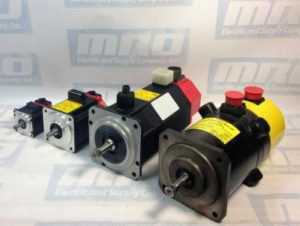
FANUC Controls Alarms

FANUC Troubleshooting Manual – FANUC CNC FAQ

FANUC CNC machine is an extremely useful tool – but like many tools, it’s susceptible to breaking. Read on to learn common FANUC issues and how to best troubleshoot to solve the problem.

What is the proper method to test a motor for a short?
The proper way to troubleshoot a FANUC motor for a short is to first lock out the machine, remove the cable from the drive, and test all three motor phases to ground with a megohmmeter. This will test both the motor and the cable for problems.

Why am I getting errors when I connect to my FANUC drive’s RS-232 port?
There are a number of explanations for these errors. The RS-323 port is a high-fail component on a FANUC drive as it is very susceptible to electrical surges. However, the RS-232 cable is also another high-fail item. Ensure that you are using a cable that is known to be functional when communicating. Otherwise when you attempt to read-in or punch-out a cable, you will get an 086 alarm that is going to indicate that the cable is incorrect, or that the port has failed.

To test whether the cable or the port has failed, take a known good cable and insert it into the RS-232 port. Next, set your machine up to receive a file. The screen should being to flash “READ”. Next, transmit your file into the machine tool. If the machine continues to flash “READ” (or “LSK” on modern controls) but never receives the file, you have a defective communications port on either the memory board or the master board. These boards or your machine will need to be sent in for repair.

What is an Axis Communications Error?
An Axis Communications Error indicates a communications problem between the motor encoder and the CNC control. This can be caused by the motor encoder itself,  the cable going to the encoder, or the axis control card the cable is plugged into.

What is an Excess Error Alarm and why is it caused?
Generally, an Excess Error means that the machine has moved beyond its allowable tolerance. The CNC has told the FANUC servo drive to make a move, the servo drive moves the motor,  which in turn moves the encoder. As the machine moves, there will be some deviation. This deviation is known as the Excess. The parameters set how much deviation/excess should be allowed.

These errors can be caused by a variety of problems. For example, a dull tool can caused the axis to be pushed out of position which results in a deviation error. Debris build up can cause deviations while the machine is stopped. Additionally, a failed servo drive can also cause deviation errors.

What is FANUC 401 Servo Alarm?
Alarm 401 is a very generic FANUC alarm. It simply means that the servo’s did not obey. The CNC, which is in charge of the servos, tells the servo drives to turn on and remain on. If for whatever reason the servo drive turns itself off without the permission from the CNC, the CNC will generate a 401 alarm. This alarm will usually occur with other alarms, such as the 414 Alarm.

What is FANUC Servo Alarm 414?
The FANUC Servo Alarm 414 is an alarm issued by the CNC that says a problem has been found in either the servo drive or the feedback system. The alarm will show which axis is causing the problem. To identify the specifics of this alarm, you must go into the CNC diagnostics page. Diagnostics number 200 on the 16th row will indicate what is causing the problem.

What is the difference between a High-Current Alarm and an Over-Current alarm?
A high current is an abnormal current that can be caused by noise. When the system detects this, it will generally shut the machine down and generate a High-Current Alarm. This FANUC alarm code is usually caused by defective servo drive or cooling contamination inside of the motor windings or cable.

An Over-Current Alarm indicates that too much current has flowed through the DC link. This is usually caused by a short in the system, an unplanned contact, a defective transistor module, or dull tooling attempting to make a cut. 

Why do I get a Soft Overtravel Alarm when I try to reference a newly installed motor?
When the CNC power down, it remembers its last known position. When you restart the machine, an incremental encoder will ask that the machine be re-positioned. When you try to do a re-reference of the machine tool, and it doesn’t agree with where the last known position was, the machine with automatically go into a default that indicates a Soft Overtravel Alarm. These alarms can occur as any point in the travel of the machine. To bypass this alarm, power the machine down and hold down the key with the letter “P” on it as well as the “Cancel” button (at the same time). Then power the machine up while you continue to hold down both of these buttons. If you do this, the machine will ignore all Soft Overtravels until the first zero referenced position has been done on that axis, and will clear the Soft Overtravel Alarms.

I unplugged my AC or DC FANUC motors, and now I am getting a 300APC Alarm. What is that?
A 300APC Alarm indicates that you are using an absolute pulse coder. The difference between an absolute pulse coder and a incremental pulse coder deals in the memory retention of the position. Using a CNC control with an incremental pulse coder, you must reference the machine every time you turn the machine back on.

With an absolute pulse coder, there is a battery backed memory that retains the position of the machine tool when it powers down. When the CNC machine turns back on, it asks the encoder its position, and the encoder then responds back with its current position. If it is within tolerance of where it was when it shut down, the CNC will continue to run the program. However, if you lose the memory retention due to an encoder cable being unplugged, you will end up with the 300 level APC alarms. These FANUC alarms simply signify that the machine must be re-referenced. The re-referencing procedure is determined by the machine tool builder – consult your machine tool builder manual for the proper operation.

If this FANUC troubleshooting manual was not comprehensive enough, MRO Electric stocks new and refurbished FANUC products, and also offers reliable FANUC repairs. Please call 800691-8511 or email sales@mroelectric.com for a quote.

micromaster 440

MicroMaster 440 Parameter List and Fault Codes

Optimize the functionality of your Siemens Micromaster 440 by checking out our parameter list and guide to understanding Micromaster 440 fault codes and alarms.

MRO Electric has new and refurbished Micromaster 440 Drives in stock. Take a look at all of our Siemens products including motors, drives, HMIs, and much more. Be sure to check out our list of Siemens Micromaster 420 fault codes as well.  

If you need assistance with your Micromaster 440, our team can also repair non-functioning drives. To request a quote, please email sales@mroelectric.com or call 800-691-8511.

Micromaster 440 Parameter List

Following parameters are needed for quick commissioning of a Micromaster 440 drive.
NoNameAccess levelCstat
P0100 Europe / North America1C
P0205Inverter application3C
P0300Select motor type2C
P0304Motor voltage rating1C
P0305Motor current rating1C
P0307 Motor power rating1C
P0308Motor cosPhi rating2C
P0309 Motor efficiency rating2C
P0310Motor frequency rating1C
P0311Motor speed rating1C
P0320 Motor magnetizing current3CT
P0335Motor cooling2CT
P0640 Motor overload factor [%]2CUT
P0700Selection of command source1CT
P1000Selection of frequency setpoint1CT
P1080Min. speed1CUT
P1082Max. speed1CT
P1120Ramp-up time1CUT
P1120Ramp-down time1CUT
P1135 OFF3 ramp-down time2CUT
P1300Control mode2CT
P1500 Selection of torque setpoint2CT
P1910Select motor data identification2CT
P3900 End of quick commissioning1C

Micromaster 440 Faults and Alarms

In the event of a failure, the inverter switches off and one of the following fault codes appear on the display.
FaultPossible CausesDiagnose & RemedyQuit
F0001
OverCurrent
- Motor power (P0307) does not correspond to the inverter power (r0206)
- Motor lead short circuit
- Earth faults
Check the following:
1. Motor power (P0307) must correspond to inverter power (r0206).
2. Cable length limits must not be exceeded.
3. Motor cable and motor must have no shortcircuits or earth faults
4. Motor parameters must match the motor in use
5. Value of stator resistance (P0350) must be correct
6. Motor must not be obstructed or overloaded
- Increase the ramp time
- Reduce the boost level
OFF2
F0002
OverVoltage
- DC-link voltage (r0026) exceeds trip level (P2172)
- Overvoltage can be caused either by too high main supply voltage or if motor is in regenerative mode. Regenerative mode can be cause by fast ramp downs or if the motor is driven from an active load.
Check the following:
1. Supply voltage (P0210) must lie within limits indicated on rating plate .
2. DC-link voltage controller must be enabled (P1240) and parameterized properly.
3. Ramp-down time (P1121) must match inertia of load.
4. Required braking power must lie within specified limits.
NOTE:
Higher inertia requires longer ramp times; otherwise, apply braking resistor.
OFF2
F0003
UnderVoltage
- Main supply failed.
- Shock load outside specified limits.
Check the following:
1. Supply voltage (P0210) must lie within limits indicated on rating plate.
2. Supply must not be susceptible to temporary failures or voltage reductions.
OFF2
F0004
Inverter Over
Temperature
- Inverter overloaded.
- Duty cycle too demanding.
- Motor power (P0307) exceeds inverter power capability (r0206).
Check the following:
1. Load duty cycle must lie within specified limits.
2. Motor power (P0307) must match inverter power (r0206)
OFF2
F0011
Motor Over
Temperature
- Motor overloaded Check the following:
1. Load duty cycle must be correct
2. Motor nominal overtemperatures (P0626-P0628) must be correct
3. Motor temperature warning level (P0604) must match
OFF1
F0012
Inverter temp.
signal lost
Wire breakage of inverter temperature (heatsink) sensorOFF2
F0015
Motor temperature
signal lost
Open or short circuit of motor temperature sensor. If signal loss is detected, temperature monitoring switches over to monitoring with the motor thermal model.OFF2
F0020
Mains Phase
Missing
Fault occurs if one of the three input phases are missed and the pulses are enabled and drive is loadedCheck the input wiring of the mains phasesOFF2
F0021
Earth fault
Fault occurs if the sum of the phase currents is higher than 5 % of the nominal inverter current.
NOTE - Framesizes D to F
This fault only occurs on inverters that have 3 current sensors.
OFF2
F0022
Powerstack fault
That hardware fault (P0947 = 22 and
P0949 = 1) caused by the following events:
(1) DC-link overcurrent = short circuit of IGBT
(2) Short circuit of chopper
(3) Earth fault
(4) I/O board is not poperly inserted.
- Framesizes A to C (1),(2),(3),(4)
- Framesizes D to E (1),(2),(4)
- FramesizeF(2),(4)
- Since all these faults are assigned to one signal on the power stack, it is not possible to establish which one actually occurred.
- UCE failure was detected, when P0947 = 22 and fault value P0949 =12 or 13 or 14, depending on UCE (for MegaMaster only)
Check the I/O board. It has to be fully pressed home. OFF2
F0023
Output fault
One phase of output is disconnectedOFF2
F0024
Rectifier Over
Temperature
- Ventilation inadequate
- Fan inoperative
- Ambient temperature is too high.
Check the following:
- Fan must turn when inverter is running
- Pulse frequency must be set to default value
- Ambient temperature could be higher than
specified for the inverter
OFF2
F0030
Fan has failed
Fan no longer working- Fault cannot be masked while options module
(AOP or BOP) is connected.
- Need a new fan.
OFF2
F0035
Auto restart after n
Auto restart fault after n-restart tryOFF2
F0040
Automatic
Calibration Failure
MICROMASTER 440 onlyOFF2
F0041
Motor Data
Identification
Failure
Motor data identification failed.
- Alarm value =0: Load missing
- Alarm value =1: Current limit level reached during identification.
- Alarm value =2: Identified stator resistance less than 0.1% or greater than 100%.
- Alarm value =3: Identified rotor resistance less than 0.1% or greater than 100%.
- Alarm value =4: Identified stator reactance less than 50% and greater than 500%
- Alarm value =5: Identified main reactance less than 50% and greater than 500%
- Alarm value =6: Identified rotor time constant less than 10ms or greater than 5s
- Alarm value =7: Identified total leakage reactance less than 5% and greater than 50%
- Alarm value =8: Identified stator leakage reactance less than 25% and greater than 250%
- Alarm value =9: Identified rotor leakage inductance less than 25% and greater than 250%
- Alarm value = 20: Identified IGBT onvoltage less than 0.5 or greater than 10V
- Alarm value = 30: Current controller at voltage limit
- Alarm value = 40: Inconsistence of identified data set, at least one
identification failed Percentage values based on the impedance Zb = Vmot,nom / sqrt(3) / Imot,nom
0: Check that the motor is connected to the inverter.
1-40: Check if motor data in P304-311 are correct. Check what type of motor wiring is required (star, delta).
OFF2
F0042
Speed Control
Optimisation Failure
- Motor data identification failed.
- Alarm value =0: Time out waiting for stable speed
- Alarm value =1: Inconsistent readings
OFF2
F0051
Parameter EEPROM
Fault
- Read or write failure while saving nonvolatile
parameter.
- Factory Reset and new parameterization
- Change drive
OFF2
F0052
power stack Fault
- Read failure for power stack information or invalid data- Change driveOFF2
F0053
IO Eeprom Fault
- Read failure for IO EEPROM information or invalid data.- Check data
- Change IO module
OFF2
F0054
Wrong IO Board
1. Wrong IO board is connected.
2. No ID detected on IO board, No data.
- Check data
- Change IO module
OFF2
F0060
Asic Timeout
- Internal communications failure- If fault persists, change inverterOFF2
F0070
CB setpoint fault
- No setpoint values from CB (communication board) during telegram off time- Check CB and communication partnerOFF2
F0071
USS (BOP-link)
setpoint fault
- No setpoint values from USS during telegram off time- Check USS masterOFF2
F0072
USS (COMM link)
setpoint fault
- No setpoint values from USS during telegram off time- Check USS masterOFF2
F0080
ADC lost input
signal
- Broken wire
- Signal out of limits
OFF2
F0085
External Fault
- External fault triggered via terminal inputs- Disable terminal input for fault trigger.OFF2
F0090
Encoder feedback
loss
- Signal from Encoder lost1. Check encoder fitted. If encoder not fitted, set P400 = 0 and select SLVC mode (P1300 = 20 or 22)
2. Check connections between encoder and inverter
3. Check encoder not faulty (select P1300 = 0, run at fixed speed, check encoder feedback signal in P66)
Increase encoder loss threshold in P492
OFF2
F0101
Stack Overflow
- Software error or processor failure- Run self test routinesOFF2
F0221
PID Feedback below
min. value
- PID Feedback below min. value P2268- Change value of P2268.Adjust feedback gain.
F0222
PID Feedback above
max. value
- PID feedback above max. value P2267.- Change value of P2267.Adjust feedback gain.
F0450
BIST Tests Failure
Fault value:
1. Some power section tests have failed
2. Some control board tests have failed
4. Some functional tests have failed
8. Some IO module tests have failed. (MM 420 only)
16. Internal RAM failed on power-up check
- Drive may run but some features will not work properly.
- Replace drive.
F0452
Belt Failure
Detected
- Load conditions on motor indicate belt
failure or mechanical fault.
Check the following:
1. No breakage, seizure or obstruction of drive train.
1. If using an external speed sensor, check for correct function.Check parameters:
- P0409 (pulse per min at rated speed).
- P2191 (Belt failure speed tolerance).
- P2192 (delay time for permitted deviation)
2. If using the torque envelope, check parameters:
- P2182 (threshold frequency f1)
- P2183 (threshold frequency f2)
- P2184 (threshold frequency f3)
- P2185 (upper torque threshold 1)
- P2186 (lower torque threshold 1)
- P2187 (upper torque threshold 2)
- P2188 (lower torque threshold 2)
- P2189 (upper torque threshold 3
- P2190 (lower torque threshold 3)
- P2192 (delay time for permitted deviation)
4. Apply lubrication if required.

Need help with your Micromaster 440 drive?

Navigate through complex Micromaster 440 parameters and fault codes with ease. MRO Electric offers comprehensive support, from detailed parameter lists to expert repair services, ensuring your drive operates at peak performance.

sinumerik 840d sl

Siemens SINUMERIK 840D SL: Product Spotlight & Alarms

The Siemens SINUMERIK 840D sl is a popular open CNC for modular and premium machining concepts with powerful and dynamic system functions that can be used for a wide range of applications. The CNC system is drive based, and can handle up to 93 axes or spindles and any number of PLC axes. The 840D sl can be used in combination with SINAMICS S120 drives and SIMATIC S7-300 PLCs. The system’s powerful hardware architecture and intelligent control systems ensure machining with the highest level of performance and precision. Additionally, there are a number of solutions that allow for easy IT integration.

The SINUMERIK 840D sl can be used for a wide range of applications including:

  • Turning
  • Milling
  • Gear Machining
  • Grinding
  • Machining Composites
  • Handles and CNC Machining using Robots
  • Nibbling, Waterjet Cutting, Laser Machining, & Plasma Machining
  • Multitasking

The SINUMERIK 840D sl has extremely high precision and performance with accuracy up to 80-bits nano. Its dynamic feed forward control ensures that following error is completely compensated for. With its superb algorithms such as Look Ahead, this system can perform at maximum speed with the same level of performance. The SINUMERIK system also minimizes idle time to keep your production levels at maximum capacity. It can handle kinematic transformations with ease, and sets the standard in energy efficiency. The SINUMERIK 840D sl has a number of integrated safety functions to protect personnel and other machines.

Below is the Siemens SINUMERIK Alarm List:

400000PLC STOP %1 Definitions: PLC not in cyclic mode. Travel with the machine is not possible. %1: 1 Ready(User program has not been started) 2 Break (User program has been interrupted) 3 Error (Other PLC alarm with PLC Stop active) Reaction: Alarm display. Remedy: Rectify other PLC alarm; Switch on menu in PLC stop position or test user program. Program Continuation: Alarm display showing cause of alarm disappears. No further operator action necessary.
400001System error %2 Definitions: %1 :Type number With this alarm, internal alarm states are displayed that, in conjunction with the transferred error number, provide information on the cause and location of the error. Reaction: PLC Stop Remedy: Notify Siemens of this error together with the error message. Program Continuation: Switch control OFF – ON.
400002System error %1 Definitions: %1 :Type number Internal error states are displayed with this alarm. An error number is also specified to provide further details about the cause and location of the error. Reaction: PLC Stop Remedy: Report this error to Siemens along with the type number. Program Continuation: Switch control OFF – ON.
400003Faulty connection to the operator panel Definitions: %1 :Type number This alarm displays that the connection to the machine control panel via the MCPA module has been interrupted. Reaction: Mode group not ready for operation Remedy: Check connection to the MCPA module. Program Continuation: Clear alarm with the Delete key or NC START.
400004Code error: %2 network %1 Definitions: %1 :Network number %2 :Internal error code, module type The user program contains an operation which is not supported by the control. Reaction: PLC Stop Remedy: Modify and reload user program. Program Continuation: Switch control OFF – ON.
400006Loss of remanent PLC data Definitions: The following causes are possible: Control handling (e.g. standard PLC deletion, power up with default values) Control handling of power up with backed up data without backing up data in advance Support time exceeded Reaction: Alarm display. Remedy: Update the data required. Program Continuation: Clear alarm with the Delete key or NC START.
400007Operand error: %2 network %1 Definitions: %1 :Network number %2 :Module type Reaction: PLC Stop Remedy: The variable displayed must be checked in the user program for violation of the address range, impermissible data type and alignment errors. Program Continuation: Switch control OFF – ON.
400008Programming tool – version is not compatible %1 %2 Definitions: %1 :Programming tool version This version is not compatible with the product version of the control system. Reaction: PLC Stop Remedy: Translate the user program using a suitable programming tool version and load in the control. Program Continuation: Switch control OFF – ON.
400009Computing time overrun at PLC level: %2 network %1 Definitions: %1 :Network number %2 :Module type Check user program of the corresponding network displayed. Reaction: PLC Stop Remedy: Change user program Program Continuation: Switch control OFF – ON.
400010Arithmetic error in user program: Type %2 network %1 Definitions: Check user program in the specified network. %1Network number, module ID %2 = 1:Division by zero using fixed-point arithmetic 2:Floating-point arithmetic Reaction: PLC Stop Remedy: Change user program. Program Continuation: Switch control OFF – ON.
400011Maximum number of subroutine levels exceeded: %2 network %1 Definitions: %1Network number %2Module ID Check user program in the specified network. Reaction: PLC Stop Remedy: Change user program. Program Continuation: Switch control OFF – ON.
400013PLC user program is incorrect Definitions: The PLC user program in the control is incorrect or is not available. Reaction: PLC Stop Remedy: Reload PLC user program. Program Continuation: Switch control OFF – ON.
400014PROFIBUS DP: power up interrupted, type: %1 Definitions: %1: 1PROFIBUS DP power up interrupted 2Software versions of NC and PLC do not match 3Number of slots per function exceeded 4PROFIBUS DP server not ready Reaction: PLC Stop Remedy: Types 1 to 3:Report error to Siemens Type 4:802D sl – Check and/or replace PCU hardware and/or check MD 11240 Program Continuation: Switch control OFF – ON.
400015PROFIBUS DP: I/O defect: log adr. %1 bus/station: %2 Definitions: The PLC-AWP is using I/O addresses which are not available. %1Logical I/O address %2Bus number/station number Causes of error: Bus peripheral has no voltage Bus address set incorrectly Bus connection faulty Active MD 11240 (SDB configuration) is set incorrectly Reaction: PLC Stop Remedy: Rectify the error using the error cause Program Continuation: Switch control OFF – ON.

The SINUMERIK 840D sl can be used in many different industries. Its customization solutions allow it to fulfill the requirements of even highly regulated industries. There are even support services and solutions provided for specific niches.
SINUMERIK 840D SL Applicatons

MRO Electric offers a variety of support services for the SINUMERIK 840D sl. These include providing new spares, refurbished components, and repair services. If you are in need of a replacement part or FANUC repairs, please call us at 800-691-8511 or email sales@mroelectric.com.
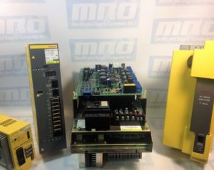
tsxcusbmbp

Schneider Electric TSXCUSBMBP: Beyond the User Manual

Need a replacement TSXCUSBMBP? Request a Price Quote Now.

The Schneider Electric TSXCUSBMBP is a USB Modbus Plus Communications Adapter. In this guide, we will show you how to install the hardware, configure the driver software, and use the Modbus Plus network diagnostics features of the driver software.

Important: The least versions of the TSXCUSBMBP driver to run on Win Server 2012 R2 are driver versions 8.0 and 8.1.

The TSXCUSBMBP is designed to bridge the gap between a USB connection and the Modbus Plus network. It combines hardware and software together in one simple and single device. The module has its own Modbus Plus node address which can be set through the TSXCUSBMBP driver software. This module allows software applications using the serial Modbus RTU communications to connect on the high-speed Modbus Plus network, as well as provide diagnostic capabilities to the Modbus Plus network.

Most Win32 Applications that support serial Mdubus communications can use a Modicon TSXCUSBMBP to connect on a Modbus Plus network. A VSP (Virtual Serial Port) is what redirects communications from Concept, Unity, ProWorx32 and other programs to the TSXCUSBMBP communications adapter. After the VSP is installed, it will create one serial port with the port reference as defined in the module’s driver software. When configuring the Modbus application software, this port reference is selected as the serial port for the application to use. The routing table is used to associate Modbus Slave IDs with 5-byte Modbus Plus routing paths which allow the application software to communicate with any Modbus Plus device within range on the network.

The TSXCUSBMBP’s hardware consists of a box with a USB cable from one end (which connects to the PC) and a standard Modbus Plus DB9 connector on the other end (for the Modbus Plus network). Local signalling LEDs on the top cover of the device tell you the presence of power from the USB port and the state of the Modbus Plus network – no external power supply is required.

TSXCUSBMBP Installation

To install the TSXCUSBMBP, you will need the following:
– Windows XP Operating System with service pack 2, or Windows 2000 with Service Pack 4 or greater.
– 1 MB of free disk space.
– Minimum of 256 MB of RAM.
– One free USB port or a USB Hub that supports USB 1.1 or greater.

If a previous version of the TSXCUSBMBP was installed, the VSP component of the driver must be manually uninstalled using Device Manager before a new version can be installed. After this, the new driver should be installed before connecting the new TSXCUSBMBP to the PC. After the new driver is installed, connect the TSXCUSBMBP and install using the New Hardware Wizard. After completing the instructions, you should see a message stating “Your new hardware is ready to use.” Restart your computer, and the device should be fully functional. If the driver starts up before the TSXCUSBMBP is connected, then it will be necessary to re-scan for adapters so the driver can detect it.

TSXCUSBMBP Configuration

To configure the module, you will need to do the following:

1. Configure the Modbus Plus Node Address
The communications adapter must be assigned a Modbus Plus node address to communicate on the network. Select “Settings” and then type the address in the appropriate box. When complete, hit “Save”.

2. Configure the Slave Response Timeout
The slave response timeout is used by the module each time it sends a request from an application out on the network to a slave device. Use the manual to determine the appropriate value that should be used with your system. Select “Settings” and then type the value in the appropriate box. When complete, hit “Save”.

3. Configure the Virtual Serial (COM) Port
To do this, select “Virtual Modbus Port.” Select the desired COM port from the list available. When complete, click “Save”.

If you experience any problems while configuring your adapter, please use the table below to determine the appropriate error code given by the LEDs, if applicable. As always, refer to the user manual for more complete information.

TSXCUSBMBP Error Codes
MRO Electric carries both New and Refurbished TSXCUSBMBP Communication Adapters. For more information on this module or to request a price quote, please call 800-691-8511 or email sales@mroelectric.com.