PLC vs. DCS: What’s the difference?

Before we get into the differences of a PLC’s and DCS’s, we need to talk about what each of them are designed to do.

What is a PLC?

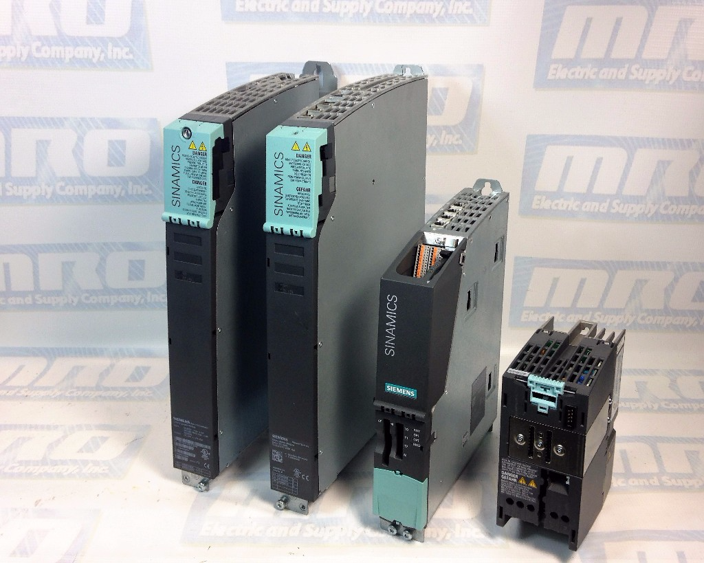
A PLC, or Programmable Logic Controller, is a computer that has been adapted to specifically meet the needs of any specific manufacturing process. These devices come in many different shapes and sizes, with many options for digital and analog I/O, as well as protection from high temperatures, vibration, and electrical noise. The invention of the PLC allowed computers to be streamlined into the industrial automation process.

A PLC can be a single device calculating and executing operations, or a rack of different modules may be used to meet whatever your automation system requires. Some of the additional components include processors, power supplies, additional IO, interfaces, and much more.  Every part works together to be able to run open or closed loop operations that are rated at high speed and high precision. Take a CNC machine for example; a PLC would be used to control positioning and motion, as well as torque control. These devices are popular because they are very inexpensive relative to the amount of power and how many hours you get out of them.

 What is a DCS?

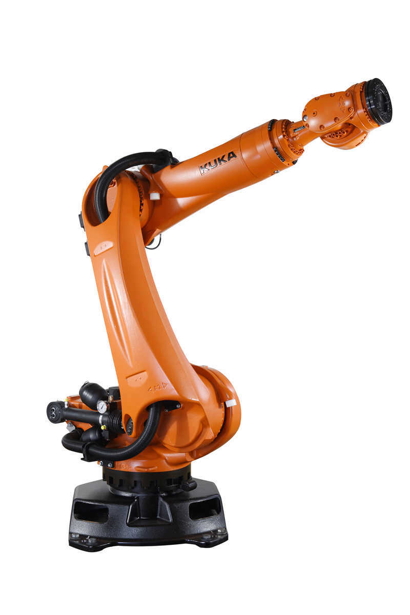
A Distributed Control System is an automated control system that streamlines the functionalities of the various devices that are used throughout an entire work space. This type of system uses many different controllers to allow all the machining parts to talk to each other as well as computers that can input parameters and display information such as power usage, speed, and much more. These controllers are distributed geographically across a plant to allow for high-speed communication to the control room. When using different types of modules however, the system may require different communication standards such as Modbus and Profibus. DCS’s started coming to fruition throughout the 1960’s once the microcomputer was brought widespread into the market.

Then what exactly is the difference?

A PLC will probably be used to control a machine that isn’t too complex wheres the DCS can have total control of all the operations in an entire plant. The PLC is preferred in situations where the machine does not have to worry about meeting specific conditions inside the plant. These conditions typically involve operations that may need to stop or restart, as well maintaining precise temperatures. A DCS will be able to take advantage of all the aspects of an automated system, from the machines and sensors to the controllers and computers. An entire DCS is much more expensive than a few PLC’s, but each have their advantages in any given situation and certain automated systems will always require one over the other.

Visit MRO Electric and Supply’s website to see all of our available Programmable Logic Controllers. If we don’t have what you need listed on the site, contact us at sales@mroelectric.com or (800)691-8511 and we will be happy to help.

ATV11-ATV12 Substitution Chart

Below is a chart that shows the direct replacement from ATV11 to ATV12 drives. MRO Electric and Supply carries new & refurbished ATV11 and ATV12 units by Schneider Electric.

ATV11 EUROPAATV11 USAATV11 ASIAATV12
-ATV11HU05F1UATV11HU05F1AATV12H018F1
ATV11HU05M2EATV11HU05M2UATV11HU05M2AАТУ12Н018М2
-ATV11HU05M3UATV11HU05M3AАТУ12Н018М3
-ATV11HU09F1UATV11HU09F1AATV12H037F1
-ATV11PU09F1UATV11PU09F1AATV12P037F1
AN11HU09M2EATV11HU09M2UATV11HU09M2AATV12H037M2
AN11PU09M2EATV11PU09M2UATV11PU09M2AATV12P037M2
-ATV11HU09M3UATV11HU09M3AATV12H037M3
-ATV11PU09M3UATV11PU09M3AATV12P037M3
ATV11HU12M2E--ATV12H055M2
ATV11PU12M2E--ATV12P055M2
-ATV11HU18F1UATV11HU18F1AATV12H075F1
ATV11HU18M2EATV11HU18M2UATV11HU18M2AАTV12H075М2
ATV11PU18M2EATV11PU18M2UATV11PU18M2AATV12P075M2
-ATV11HU18M3UATV11HU18M3AАTV12H075М3
-ATV11PU18M3UATV11PU18M3AATV12P075M3
ATV11HU29М2ЕATV11HU29M2UATV11HU29M2AATV12HU15M2
-ATV11HU29M3UATV11HU29M3AATV12HU15M3
ATV11HU41M2EATV11HU41M2UATV11HU41M2AATV12HU22M2
-ATV11HU41M3UATV11HU41M3AATV12HU22M3

MagneTek GPD503 Fault Codes

Below is a chart with fault codes regarding the MagneTek G3 GPD503 series drives. MRO Electric and Supply offers free evaluations on units. You can find our RMA form on our repair page. Follow us on Twitter @MROElectric for updates on new products and find any deals we may have.

bbExternal Base Block command
Base Block command at multi-function terminal is active, shutting off GPD 503 output (motor coasting). Temporary condition, cleared when input command is removed.
bUSTransmission error
Control data cannot be received normally for longer than 2 seconds.
CALLCommunication ready
Drive is waiting for the PLC to establish communication.
CPF00Transmission error or control function hardware fault (including internal RAM, external RAM or PROM)
Transmission between GPD 503 and remote operator is not established within 5 seconds after the power supply is turned on. (Displayed on the remote operator.)
CPF01Transmission error
Transmission error occurs 2 seconds or more after transmission has first been established.
CPF02Base block circuit failure
GPD 503 failure.
CPF03NV-RAM (S-RAM) fault
GPD 503 failure.
CPF04NV-RAM (BCC, Access Code)
fault
GPD 503 failure. This fault may be caused after changing EPROM chips. Perform a Sn-03 Reset operation to attempt to clear this fault.
CPF05A/D converter failure in CPU
GPD 503 failure.
CPF06Optional connection failure
Improper installation or wiring of option card.
CPF20A/D converter failure
Defective option card.
CPF21Transmission interface card (option) self-analysis function fault
Defective option card. Check option card connector for proper installation.
CPF22Model code fault
Defective option card. Check option card connector for proper installation.
CPF23Mutual-analysis function fault
Defective option card. Check option card connector for proper installation.
EF (blinking)Simultaneous forward and reverse operation commands
Fwd Run and Rev Run commands are both closed for more than 500 ms. Removing one command will allow drive operation.
EF0External fault
GPD 503 is in Stop mode.
EF3Ext. fault signal at term. 3
A fault condition has occurred in the external circuit(s) monitored by the contact providing input to the indicated terminal. If display is steady, GPD 503 is in Stop mode; if display is blinking, the terminal is programmed to allow continued operation after receiving fault input.
EF5Ext. fault signal at term. 5
A fault condition has occurred in the external circuit(s) monitored by the contact providing input to the indicated terminal. If display is steady, GPD 503 is in Stop mode; if display is blinking, the terminal is programmed to allow continued operation after receiving fault input.
EF6Ext. fault signal at term. 6
A fault condition has occurred in the external circuit(s) monitored by the contact providing input to the indicated terminal. If display is steady, GPD 503 is in Stop mode; if display is blinking, the terminal is programmed to allow continued operation after receiving fault input.
EF7Ext. fault signal at term. 7
A fault condition has occurred in the external circuit(s) monitored by the contact providing input to the indicated terminal. If display is steady, GPD 503 is in Stop mode; if display is blinking, the terminal is programmed to allow continued operation after receiving fault input.
EF8Ext. fault signal at term. 8
A fault condition has occurred in the external circuit(s) monitored by the contact providing input to the indicated terminal. If display is steady, GPD 503 is in Stop mode; if display is blinking, the terminal is programmed to allow continued operation after receiving fault input.
ErrConstant write-in fault
Temporary display, in Program mode, indicating that constant setting was not written into EPROM memory.
FAnCooling fan failure
GPD 503 is in Stop mode.
FUFuse blown
DC Bus fuse has cleared. Check for short circuit in output, and check main circuit transistors.
GFGround fault protection
Ground current > approx. 50% of the GPD 503 rated current.
oCOvercurrent
GPD 503 output current exceeds 200% of GPD 503 rated current, or ground fault has occurred, with ground current exceeding 50% of GPD 503 rated current.
oHHeat sink overheated
Fin temperature exceeds 90° C (194° F)
oH2 (blinking)External overheat
External temperature monitoring circuit(s) detected an overtemperature condition and produced an input signal.
oL1Overload
Thermal motor overload protection has tripped.
oL2Overload
GPD 503 overload protection has tripped.
oL3 (blinking)Overload
GPD 503 output torque exceeds the set Overtorque Detection level, but GPD 503 is programmed for continued operation at overtorque detection.
oL3Overload
GPD 503 output torque exceeds the set Overtorque Detection level, and GPD 503 is programmed for coast to stop at overtorque detection.
oPE01kVA constant setting fault
Sn-01 setting is incorrect.
oPE02Constant setting range fault
An-XX, bn-XX, Cn-XX, or Sn-XX setting range fault.
oPE03Constant set value fault
Sn-15 to -18 (multi-function input) set value fault.
oPE04Constant set value fault
PG constant, number of poles, or PG division rate set incorrectly.
oPE10Constant set value fault
Cn-02 to -08 (V/f data) set incorrectly.
oPE11Constant set value fault
One of the following conditions was detected: • Cn-23 > 5 KHz and Cn-24 5 KHz or • Cn-25 > 6 and Cn-24 > Cn-23
ou (blinking)Overvoltage
Internal monitor of DC Bus voltage indicates that input AC power is excessively high, while GPD 503 is in stopped condition.
ouOvervoltage (OV)
Detection level: Approx. 400V for 230V; Approx. 800V for 460V; Approx. 1000V for 575V.
rrRegenerative transistor Failure
Dynamic Braking resistor has failed.
rHBraking resistor unit overheated
Dynamic Braking resistor has overheated.
Uu (blinking)Low voltage (Power UV)
Internal monitor of DC Bus voltage indicates that input AC power is below Undervoltage detection level, while the GPD 503 is in stopped condition.
Uu1 Low voltage (Power UV)Occurs two seconds after detection of low voltage.
Uu2 Low voltage UVControl circuit voltage levels drop below acceptable levels during operation.
Uu3 Low voltage (MC-ANS fault)Main circuit magnetic contactor does not operate correctly.

Yaskawa P1000 Fault Codes

Below is a table of common fault codes found on Yaskawa P1000 units. If problems continue to occur, it may be worth replacing your unit. MRO Electric specializes in Yaskawa repair, as well as unit distribution, if you are interested in obtaining a new or refurbished P1000 unit.

bATDigital Operator Battery Voltage Low - The digital operator battery is low Replace the digital operator battery.
boLBraking Transistor Overload Fault - The wrong braking resistor is installed Select the correct braking resistor.
bUSOption Communication Error - No signal was received from the PLC. Check for faulty wiring.
CE MEMOBUS/Modbus Communication Error - Faulty communications wiring or an existing short circuit.
CEMEMOBUS/Modbus Communication Error - Faulty communications wiring or an existing short circuit.
CPF02A/D Conversion Error - Control circuit is damaged. Replace the control board or the entire drive.
CPF03Control Board Connection Error - Turn off the power and check the connection between the control board and the drive.
CPF06EEPROM Memory Data Error - Turn off the power and check the connection between the control board and the drive.
CPF07Terminal Board Connection Error - Faulty connection between the terminal board and the control board. Turn off the power and reconnect the terminal board.
CPF08Terminal Board Connection Error - Faulty connection between the terminal board and the control board. Turn off the power and reconnect the terminal board.
CPF11Control Circuit Error - Hardware is damaged. Cycle Power. Replace hardware.
CPF12Control Circuit Error - Hardware is damaged. Cycle Power. Replace hardware.
CPF13Control Circuit Error - Hardware is damaged. Cycle Power. Replace hardware.
CPF14Control Circuit Error - Hardware is damaged. Cycle Power. Replace hardware.
CPF15Control Circuit Error - Hardware is damaged. Cycle Power. Replace hardware.
CPF16Control Circuit Error - Hardware is damaged. Cycle Power. Replace hardware.
CPF17Control Circuit Error - Hardware is damaged. Cycle Power. Replace hardware.Control Circuit Error - Hardware is damaged. Cycle Power. Replace hardware.
CPF18Control Circuit Error - Hardware is damaged. Cycle Power. Replace hardware.
CPF19Control Circuit Error - Hardware is damaged. Cycle Power. Replace hardware.
CPF20Control Circuit Error - Hardware is damaged. Cycle Power. Replace hardware.
CPF21Control Circuit Error - Hardware is damaged. Cycle Power. Replace hardware.
CPF22Hybrid IC Error - Hardware is damaged. Cycle Power. Replace hardware.
CPF23Control Board Connection Error - Hardware is damaged. Cycle Power. Replace hardware.
CPF24Drive Unit Signal Fault - The drive capacity cannot be detected correctly. Cycle Power. Replace hardware.
CPF25Terminal Board Not Connected - Hardware is damaged. Cycle Power. Replace hardware.
CPF26Control Circuit Error - Hardware is damaged. Cycle Power. Replace hardware.
CPF27Control Circuit Error - Hardware is damaged. Cycle Power. Replace hardware.
CPF28Control Circuit Error - Hardware is damaged. Cycle Power. Replace hardware.
CPF29Control Circuit Error - Hardware is damaged. Cycle Power. Replace hardware.
CPF30Control Circuit Error - Hardware is damaged. Cycle Power. Replace hardware.
CPF31Control Circuit Error - Hardware is damaged. Cycle Power. Replace hardware.
CPF32Control Circuit Error - Hardware is damaged. Cycle Power. Replace hardware.
CPF33Control Circuit Error - Hardware is damaged. Cycle Power. Replace hardware.
CPF34Control Circuit Error - Hardware is damaged. Cycle Power. Replace hardware.
CPF35Control Circuit Error - Hardware is damaged. Cycle Power. Replace hardware.
CPF40Control Circuit Error - Hardware is damaged. Cycle Power. Replace hardware.
CPF41Control Circuit Error - Hardware is damaged. Cycle Power. Replace hardware.
CPF42Control Circuit Error - Hardware is damaged. Cycle Power. Replace hardware.
CPF43Control Circuit Error - Hardware is damaged. Cycle Power. Replace hardware.
E5SI-T3 Watchdog Timer Error - Data has not been received from the PLC Execute DISCONNECT or ALM_CLR, then issue a CONNECT command or SYNC_SET command.
EF0Option Card External Fault - An external fault condition is present. Check external causes.
EF1External Fault Terminal S1 - An external fault condition is present. Check external causes. Bad S1 Terminal.
EF2External Fault Terminal S1 - An external fault condition is present. Check external causes. Bad S1 Terminal.
EF3External Fault Terminal S1 - An external fault condition is present. Check external causes. Bad S1 Terminal.
EF4External Fault Terminal S1 - An external fault condition is present. Check external causes. Bad S1 Terminal.
EF5External Fault Terminal S1 - An external fault condition is present. Check external causes. Bad S1 Terminal.
EF6External Fault Terminal S1 - An external fault condition is present. Check external causes. Bad S1 Terminal.
EF7External Fault Terminal S1 - An external fault condition is present. Check external causes. Bad S1 Terminal.
EF8External Fault Terminal S1 - An external fault condition is present. Check external causes. Bad S1 Terminal.
ErrEEPROM Write Error - Noise has corrupted data. Cycle power. Correct the parameter.
FAnInternal Fan Fault - Internal cooling fan has malfunctioned. Check for fan operation.
FbHExcessive PID Feedback - PID feedback input is greater than the level set to. Check parameter.
FbLPID Feedback Loss - Check parameter. There is a problem with the feedback sensor.
GFGround Fault - A current short to ground exceeded 50% of rated current on the output side of the drive. Check motor/cables.
LFOutput Phase Loss - Phase loss on the output side of the drive. Check motor/cables.
LF3Power Unit Output Phase Loss 3 - Phase loss on the output side of the drive. Check motor/cables.
nSENode Setup Error - A terminal assigned to the node setup function closed during run.
oCOvercurrent - Output current greater than the specified overcurrent level. Check parameter. Check motor.
oFA01Option Card Fault - The option card connection is faulty. Check connection. Replace hardware.
oFA03Option Card Fault - The option card connection is faulty. Check connection. Replace hardware.
oFA04Option Card Fault - The option card connection is faulty. Check connection. Replace hardware.
oFA05Option Card Fault - The option card connection is faulty. Check connection. Replace hardware.
oFA06Option Card Fault - The option card connection is faulty. Check connection. Replace hardware.
oFA10Option Card Fault - The option card connection is faulty. Check connection. Replace hardware.
oFA11Option Card Fault - The option card connection is faulty. Check connection. Replace hardware.
oFA12Option Card Connection Error - The option card connection is faulty. Check connection. Replace hardware.
oFA13Option Card Connection Error - The option card connection is faulty. Check connection. Replace hardware.
oFA14Option Card Connection Error - The option card connection is faulty. Check connection. Replace hardware.
oFA15Option Card Connection Error - The option card connection is faulty. Check connection. Replace hardware.
oFA16Option Card Connection Error - The option card connection is faulty. Check connection. Replace hardware.
oFA17Option Card Connection Error - The option card connection is faulty. Check connection. Replace hardware.
oFA30Option Card Connection Error - The option card connection is faulty. Check connection. Replace hardware.
oFA31Option Card Connection Error - The option card connection is faulty. Check connection. Replace hardware.
oFA32Option Card Connection Error - The option card connection is faulty. Check connection. Replace hardware.
oFA33Option Card Connection Error - The option card connection is faulty. Check connection. Replace hardware.
oFA34Option Card Connection Error - The option card connection is faulty. Check connection. Replace hardware.
oFA35Option Card Connection Error - The option card connection is faulty. Check connection. Replace hardware.
oFA36Option Card Connection Error - The option card connection is faulty. Check connection. Replace hardware.
oFA37Option Card Connection Error - The option card connection is faulty. Check connection. Replace hardware.
oFA38Option Card Connection Error - The option card connection is faulty. Check connection. Replace hardware.
oFA39Option Card Connection Error - The option card connection is faulty. Check connection. Replace hardware.
oFA40Option Card Connection Error - The option card connection is faulty. Check connection. Replace hardware.
oFA41Option Card Connection Error - The option card connection is faulty. Check connection. Replace hardware.
oFA42Option Card Connection Error - The option card connection is faulty. Check connection. Replace hardware.
oFA43Option Card Connection Error - The option card connection is faulty. Check connection. Replace hardware.
oFb00Option Card Connection Error - The option card connection is faulty. Check connection. Replace hardware.
oFb01Option Card Error - The option card connection is faulty. Check connection. Replace hardware.
oFb02Option Card Error - The option card connection is faulty. Check connection. Replace hardware.
oFb03Option Card Error - The option card connection is faulty. Check connection. Replace hardware.
oFb11Option Card Error - The option card connection is faulty. Check connection. Replace hardware.
oFb12Option Card Connection Error - The option card connection is faulty. Check connection. Replace hardware.
oFb13Option Card Connection Error - The option card connection is faulty. Check connection. Replace hardware.
oFb14Option Card Connection Error - The option card connection is faulty. Check connection. Replace hardware.
oFb15Option Card Connection Error - The option card connection is faulty. Check connection. Replace hardware.
oFb16Option Card Connection Error - The option card connection is faulty. Check connection. Replace hardware.
oFb17Option Card Connection Error - The option card connection is faulty. Check connection. Replace hardware.
oFC00Option Card Connection Error - The option card connection is faulty. Check connection. Replace hardware.
oFC01Option Card Error - The option card connection is faulty. Check connection. Replace hardware.
oFC02Option Card Error - The option card connection is faulty. Check connection. Replace hardware.
oFC03Option Card Error - The option card connection is faulty. Check connection. Replace hardware.
oFC11Option Card Error - The option card connection is faulty. Check connection. Replace hardware.
oFC12Option Card Connection Error - The option card connection is faulty. Check connection. Replace hardware.
oFC13Option Card Connection Error - The option card connection is faulty. Check connection. Replace hardware.
oFC14Option Card Connection Error - The option card connection is faulty. Check connection. Replace hardware.
oFC15Option Card Connection Error - The option card connection is faulty. Check connection. Replace hardware.
oFC16Option Card Connection Error - The option card connection is faulty. Check connection. Replace hardware.
oFC17Option Card Connection Error - The option card connection is faulty. Check connection. Replace hardware.
oFC50Option Card Error - The option card connection is faulty. Check connection. Replace hardware.
oFC51Option Card Error - The option card connection is faulty. Check connection. Replace hardware.
oFC52Option Card Error - The option card connection is faulty. Check connection. Replace hardware.
oFC53Option Card Error - The option card connection is faulty. Check connection. Replace hardware.
oFC54Option Card Error - The option card connection is faulty. Check connection. Replace hardware.
oFC55Option Card Error - The option card connection is faulty. Check connection. Replace hardware.
oHHeatsink Overheat - Check ambient temperature. Check parameter setting.
oH1Heatsink Overheat - Check ambient temperature. Check parameter setting.
oH4Motor Overheat Fault (PTC input) - Check ambient temperature. Check parameter setting.
oH5Motor Overheat Fault (NTC input) - Check ambient temperature. Check parameter setting.
oL1Motor Overload - Load heavy. Increase accel or decel time.
oL2Drive Overload - Load heavy. Increase accel or decel time.
oL3Overtorque Detection 1 - current has exceeded the value set for torque detection. Check parameter setting.
oL4Overtorque Detection 2 - current has exceeded the value set for torque detection. Check parameter setting.
oL7High Slip Braking oL - Use braking resistor. Reduce decel time.
oPrOperator Connection Fault - The external operator has been disconnected from the drive.
ovOvervoltage - Deceleration time is too short and regenerative energy is flowing from the motor into the drive. Increase decel time.
PFInput Phase Loss - Drive input power has an open phase or has a large imbalance.
rFBraking Resistor Fault - The resistance of the braking resistor is too low.
rHDynamic Braking Resistor - Deceleration time is too short and excessive regenerative energy is flowing back into the drive.
rrDynamic Braking Transistor - The braking transistor is damaged. Cycle power to the drive and check for reoccurrence of the fault.
SCIGBT Short Circuit or Ground Fault - IGBT failure. Cycle power to the drive and check for reoccurrence of the fault.
SErToo Many Speed Search Restarts - Parameters related to Speed Search are set to the wrong values.
TdETime Data Error - An error has occurred in the real-time clock. Replace digital operator.
THoThermistor Disconnect - The thermistor that detects motor temperature has become disconnected.
TIETime Interval Error - An error has occurred in the real-time clock. Replace digital operator.
TIMTime Not Set - Set time in parameter o4-17.
UL3Undertorque Detection 1 - Current is below the minimum set value. Check parameter setting.
UL4Undertorque Detection 2 - Current is below the minimum set value. Check parameter setting.
UL6Motor Underload - Current is below the minimum set value. Check parameter setting.
UnbCCurrent Unbalance - Current flow has become unbalanced. Check for damaged transistors.
Uv1Undervoltage - DC Bus Undervoltage. Check parameter setting. Input phase loss.
Uv2Control Power Supply Undervoltage - Voltage is too low for the control drive input power. Ride-through power loss.
Uv3Soft Charge Circuit Fault - Precharge relay or resistor fault. Bad precharge.
Uv4Gate Drive Board Undervoltage - Voltage drop in the gate drive board circuit. Cycle power to see if fault reoccurs.
voFOutput Voltage Detection Fault - Problem detected with the voltage on the output side of the drive.
vToLVT Overload - The output current of the drive has been elevated for a set length of time.

Encounter a fault code on your Yaskawa P1000 drive?

MRO Electric is here to guide you through the process of identifying and rectifying any issues, with an extensive selection of Yaskawa products and top-tier repair services to choose from.

Control Techniques Manufacturer Showcase

Established in 1972 in Newtown, Wales, this industrial part manufacturer owned by the Nidec Corporation continues to provide high quality AC Drives and motor control management products today. In this post, we will be showcasing some of the classes and parts Control Techniques has to offer.

Unidrive
The Unidrive line of products from Control Techniques includes devices like brushless AC servo motors. The Unidrive Classic series drives are available in five different sizes and twenty-six different models, allowing you to fit one of these devices in almost any existing automation system. This series of drives have enough built in parameters to meet most task demands.

UNI2403 by Control Techniques

The Unidrive Classic series offers complete I/O configurability, advanced position control, programmable logic functions, regeneration mode for four-quadrant operations, high speed communications for quick feedback, preset macros for simplified operations and more.

Focus DC
The Focus DC line of products are solid state analog DC drives built to last reliably in almost all environments. This family has regenerative models and different enclosure kits available to offer a wide range of custom configurations. Optional kits for these drives include ones that offer toggle switches, signal isolation, M contactor kits, dynamic braking and tachometer feedback modules.

Commander SE
The Commander SE line of products offer flexibility in many automated systems by being the top choice for microdrives. They are built to be rugged machines that can stay physically stable and constantly sit at correct temperatures. These devices are shipped with shipped with firmware that makes first time setup and installation as easy as possible, including the parameters that immediately meet the needs of most drive applications.

Commander SE products by Control Techniques

The Commander SE series offers full control of all levels of parameters, visualization of terminal connections, multiple motor speed preset settings, open loop vector control, fully configurable analog/digital Input/Output settings, sequenced switching between multiple parameters and communications via DeviceNet, PROFIBUS DP and Interbus S.

Unidrive SP
The Unidrive SP series comes in both free-standing and modular forms. The SP modular offers all the benefits of the normal Unidrive SP system along with more intense system power configurations. It is easily able to be connected together to create almost any custom setup necessary. Parallel drives are used together for higher powered motors. These drives are built to last and are flexible.

Some additional modules include SPMA AC in / DC out Drive, SPMC AC in / DC out Rectifier, SPMD DC in / AC out Inverter, SM Control MASTER, SM Control SLAVE, SPM Power Selector.

MRO Electric and Supply offers a variety of new and refurbished Control Techniques devices. We also offer repair pricing. For more information, please call 800-691-8511 or email sales@mroelectric.com.

Product Spotlight: Square D EDB34030 Circuit Breaker

The Square D EDB34030 is a three pole, 30 Ampere circuit breaker. At 277V, this miniature breaker is reliable, sustainable, efficient and safe.

Part Number: EDB34030
Item Weight: 3.6lbs
Product Dimensions: 9.7 x 6.1 x 4.5 inches
Voltage: 480V
Amperage: 30A
Trip Rating; 875A
Mounting Mode: Bolt-on
Interruption Rating: 18kA

Square D EDB breakers by Schneider Electric are available in a range of amperages varying from 20A to 60A. This particular model, the EBD34030, is 30A.
This breaker is set apart from other breakers because of its compact size at 9.7 x 6.1 x 4.5 inches, while the typical breaker is around 8 x 8 x 12 inches. As a bolt on mount, it is preferred in commercial and industrial applications where vibrations might be considered an issue. When installing, be sure to use the recommended #12-#6 AWG AI or #14-#6 AWG Cu Lug wire. This breaker is ideal for NF series panel-boards to offer superior overload and short circuit stability by utilizing thermal magnetic protection. It is also HACR rated, UL listed and CSA certified.

MRO Electric and Supply stocks Square D circuit breakers, including the EDB34030. For more information or to request a quote, please contact us at 800-691-8511 or at sales@mroelectric.com.

What are circuit breakers?

A circuit breaker is a preventative safety device that detects and stops a circuit if the current is insufficient or in excess. These devices help insure the stability of the electric current in our buildings. Unlike fuses, breakers are reusable and can be consistently relied upon to break a circuit to protect us from potential electrical fires.

How do they work?

A breaker is comprised of a few basic components. A switch is connected to an electromagnet that allows electricity to flow from the bottom to the top terminals.

Source:
http://spmphysics.onlinetuition.com.my/2008/06/uses-of-electromagnet-circuit-breaker.html

With current running through the electromagnet, it becomes magnetized. If the current is suddenly increased, the magnet becomes strong enough to pull down a metal lever attached to the switch linkage. By doing so, the contacts are broken and the electricity is powered off.

What’s the difference between certain breakers?

Residential Circuit breakers- Used in common household wiring to protect electrical appliances like refrigerators, washing machines and fans. Electrical panels can also be designed to have one breaker controlling one specific or multiple outlets in a room that shut off when overloaded.

Industrial Circuit breakers- Used with much larger electrical current applications for warehouses, factories, and other large industrial locations. They can be used to insure safety of the plant equipment, lighting, business systems, air conditioning and wiring.

Voltage– Describes the ‘pressure’ of the electricity. The most common voltages of breakers are . Most household voltage is 120V, with larger appliances around 240V.
Amperage– Measures strength of the current in amperes. Common amperages include 15A, 20A, 25A, up to 6000A.
Pole number– Describes the number of completely separate circuits that can be protected by a circuit breaker at the same time. These include single-pole, double-pole, triple-pole and tandem pole breakers.
Installation location/External Design– Breakers can be designed to be indoor or outdoor based on the application. Different enclosures can be made to withstand different weather conditions.
Interrupting Mechanism– Other breaker designs include air circuit, oil circuit, vacuum circuit, MCB, MCCB, GFI, GFCI and AFCI breakers. While these all serve the same purpose of breaking electrical current in the event of unstable electric power consumption, they have different means of interrupting the current.


Visit MRO Electric and Supply’s website to see all of our available Circuit Breakers. If we don’t have what you need listed on the site, contact us at sales@mroelectric.com or (800)691-8511 and we will be happy to help.