The CNC (Computer Numerical Control) spindle motor has been a crucial tool in the world of industrial automation. Its creation has revolutionized the way industrialization functions and has led to increased quality control and productivity overall. The impact of this revolutionary tool in industrial automation is a game changer. With a spindle motor, production can be faster, more efficient, and lower in cost.
The History of CNC
The development of the CNC (Computer Numerical Control) spindle motor is closely linked to the history of CNC technology itself. The first CNC machines were developed in the 1940s and 1950s for the aerospace industry. In the early days of CNC, spindle motors were typically DC motors with brushes. These had limited speed control and were prone to wear and tear. However, as technology advanced, new spindle motors became developed. This included AC motors and brushless DC motors, which offered higher efficiency, greater reliability, and improved speed control. Today, spindle motors are an essential component of CNC machines, driving the tool and controlling the cutting process to achieve high levels of precision and efficiency.
During the 1970s, the development of the CNC (Computer Numerical Control) spindle motor was still in its early stages. According to an article by CNC Masters, spindle motors of the time were typically DC motors with brushes, which offered limited speed control and were prone to wear and tear. Despite these limitations, the introduction of CNC technology represented a significant advance in the machining industry, allowing for greater precision and efficiency. As CNC machines became more widely adopted, the demand for improved spindle motors grew, leading to the development of new types of motors that offered higher efficiency, greater reliability, and improved speed control. Today, spindle motors are a critical component of CNC machines and have come a long way since the early days of the
CNC Advantages
The advantages of CNC spindle motors make them an essential component in modern CNC machines, helping to improve accuracy, productivity, and efficiency in manufacturing operations.
- Precision: CNC spindle motors provide high levels of accuracy and precision in machining operations. Lower vibrations also factor into increased accuracy. Fewer vibrations on the bearings and rotor make for a more accurate CNC.
- Power: CNC spindle motors can generate high torque. This enables them to handle tough materials and make deep cuts. This is especially important in heavy-duty machining applications, where a lot of material needs quick and efficient removal.
- Reliability: Built for durability, CNC spindle motors can withstand the rigors of industrial use. Constructed using high-quality materials, they can operate under high loads and high temperatures.
- Low Maintenance: CNC spindle motors are designed with minimal need for lubrication or adjustment. This helps to reduce downtime and maintenance costs, allowing manufacturers to increase productivity and efficiency.
- Versatility: CNC spindle motors are available in various sizes and power ratings, making them versatile and suitable for a wide range of machining applications. They can be used with various cutting tools, including drills, end mills, and routers, making them suitable for cutting a range of materials, from metals to plastics.
Spindle Motor Types
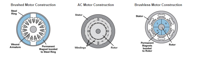
CNC Spindle Motors are generally broken down into two types: AC Induction and DC Brushless motors.
With AC induction motors, alternating current generates a magnetic field in the stator windings. This magnetic field then interacts with the rotor and creates torque in the motor drive. AC induction motors tend to be more robust and built tough to meet the demands of industrial applications.
In contrast to AC motors, DC brushless motors use direct current to generate a similar magnetic field in the stator windings. However, a DC motor contains magnets on the rotor that moves to create torque. The advantage of this design is that no friction is being created in the process thereby avoiding a lot of the wear and tear caused by heat and friction. This results in a reliable and long-lasting motor.
Conclusion
As population and demand increase, the need for CNC will continue to increase with it. Over the years this manufacturing tool has proven its value through its speed, reliability, productivity, and efficiency. This trend will likely be the case for years on end.