When installing a new Sinumerik or Simodrive unit, there is a specific set of checks that you should go through to make sure that everything is functioning properly. Siemens issues the following check list, and we always recommend that people go through the list to avoid any possible issues with a new installation.
Category: Troubleshooting & Repair
Siemens Sinumerik Drive and I/O Alarms
For troubleshooting your Siemens Sinumerik system, here is a list of the Siemens Sinumerik Drive and I/O Alarms directly from the Sinumerik manual. For more info, give us a call at 800-691-8511 or email sales@mroelectric. Our full Sinumerik series is listed here.
Drive and I/O alarms
Alarms
334 Diagnostics Manual, 03/2011, 6FC5398-2CP10-3BA0
300411 Axis %1 drive %2 error when reading a file (%3, %4)
Parameters: %1 = NC axis number
%2 = Drive number
%3 = Error code 1
%4 = Error code 2
Read More
Modbus Plus and SY MAX Ethernet Network Errors
SY/MAX Ethernet transaction function error codes for Modbus Plus appear as Mmss, where M is the high code, m is the low code, and ss is the subcode. Read below for information regarding possible Schneider Module Modbus Plus and SY MAX Ethernet Network Errors.
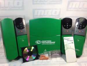
Control Techniques UNIDRIVE Alarm and Status Indications

When there is a critical condition detected in your Control Techniques UNIDRIVE, the drive will continue to operate, but the lower display’s status indication will be replaced by an alarm indication. When an HF trip takes place, the Drive Healthy relay will open and serial communications will not function. It is important to give attention to alarm indications, because if an issue is not corrected, the drive could trip.
Refer to the guide below to help identify what kind of error your UNIDRIVE may be experiencing. A comparison chart with status indications is also provided to help identify what happens at each stage of operation.
Read More
Booting the Siemens PCU 20 and PCU 50
When booting the Siemens PCU that you have installed, it should be a relatively simple process, but there can be some problems that come up, so we wanted to go through a few to help anyone who is having issues. When the power supply is switched on, the PCU boots automatically. The system software is installed in the factory and is ready to run. The basic display appears on the screen if the MMC has booted successfully
Reloading Siemens Sinumerik Start-up Archive Files
Reloading Siemens Sinumerik Start-up Archive Files for the NC and PLC
1. Using OP, (Operator Panel) select hardkey Machine then Menu select
Observe: The main operating areas horizontal softkey menu appears. Machine, Parameter, Program, Services, Diagnosis and Start-up.
2. Using OP, select softkey Services
Observe: Current operating area is displayed at top left of display.
3. Using OP, select the hardkey (etc…/extension of the softkey menu key).
Observe: Horizontal softkey menu contains a key labeled Series start-up
NOTE: If softkey Series start-up does not appear then the password access rights need to be set. See the procedure Setting Password Access rights Page 3.
4. Using OP, select horizontal softkey Series start-up.
Observe: Display shows ‘Create series startup archive’ window.
NOTE: If Display shows Read startup archive window, skip step 5
5. Using OP, select vertical softkey Read start-up archive
Observe: A new window will appear, labeled Read Series Start-up Archive.
6. Using OP cursor keys highlight the appropriate NC or PLC archive file.
Note: The backup files are created by the builder and / or end user and the specific name may vary. Suggestion: Select a file which refers to the NC or PLC and has the most recent date
7. Using OP, press the vertical softkey Start.
Observe: The window will shift to the Job Log display. a. Answer the query ‘Do you wish to perform a series start-up?’ By pressing the vertical softkey Yes. b. A series of prompts will appear, telling you the status of the upload of the various series start-up files from the NC archive. c. The message ‘NC Reset – Please wait’ will now appear as many as 6 times. This is normal. d. The control will shift back to the Read Series Start-up Archive display.
8. If necessary, repeat steps 6 and 7, selecting the appropriate archive file, to load both the NC and the PLC.
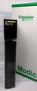
Assigning a 140 NOE Module Ethernet Address Parameter

If you have just received the Schneider 140 NOE 771 xx module but have not yet programmed it with an Ethernet configurable extension, you will need to assign an IP address to your module. In this guide you’ll receive information about assigning a 140 NOE Module Ethernet Address Parameter.
Using the BOOTP Lite software utility you can assign IP address parameters. One thing to note, however, is that with the modules 140 NOE 771 01, -11, and NWM 100 00 you can assign the IP address using web pages.
Read More