The Control Techniques UD73 large option module is a high speed microprocessor that provide a low cost facility for a system designer to write app specific programs without needing a PLC or other stand-alone controllers. The module is programmed via the RS232 port using the Control Techniques system programming toolkit.
The UD73 module uses a dual port RAM to interface to the drive’s main processor which provides intimate high-speed bi-directional access. It can ready and modify any of the parameters within the drive. This enables customized real-time calculations under a multi-tasking run-time environment.
The optically isolated RS485 port serves as a communication for for the CTIU operator interface units. It is fully configurable, supporting many communication modes. In addition, the module has the Profibus-DP port for additional communication options.
For additional info you can visit the UD73 product page on our website here. We will continue to post info about the Control Technique option modules in the future. If you would like to order a module or get more info you can email sales@mroelectric.com or call 1-800-691-8511.
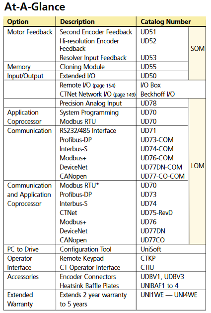
The table below shows a quick reference for all of the different option modules that can be used with the Unidrive Classic series. We have all of the different modules available and in stock.
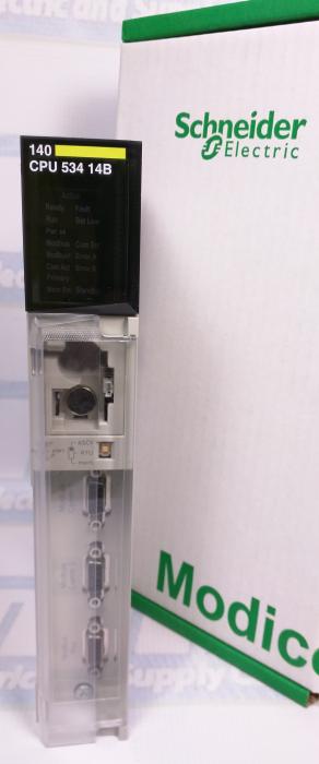
The Modicon Quantum 140CPU53414B is a Schneider Electric CPU module which is supported by Concept and ProWORX software. The CPU can also be used with Unity by upgrading the exec file. This CPU is currently at the forefront of the Quantum series and one of the more popular CPUs for many PLC systems.
On the front of the 140CPU53414B there are two switches, a three-position slide switch and a three-position key switch. The slide switch is used to select the comm parameter settings for the Modbus RS-232 ports. Setting the slide switch to the top position assigns ASCII functionality to the port.
We will be continuing a series with more info on the 140CPU53414B along with troubleshooting info the the CPU, as anyone who has had their CPU go down knows the price of their line being out of commission. For more technical data you can check out the PDFs on our site that include the manual for the Quantum series.
The Quantum 140CPU43412A CPU is a single-slot programmable controller with built-in executive memory, application memory and communication ports. All memory components are on board so no additional chips or cartridges are necessary.
Quantum CPUs use flash memory technology to support the CPU’s executive memory and instruction set. Flash is a state-of-the-art, nonvolatile memory technology that enables downloadable field upgrades as new features become available.
The application program can be stored in either battery-backed RAM and/or Flash RAM. The battery is located on the front of the CPU and can be serviced while the CPU is running. To protect the application program from inadvertent changes during operation, the 140CPU43412A features a memory-protect switch. An LED goes on when this switch is activated.
The 140CPU43412A CPU has two Modbus® ports and one Modbus Plus™ port. Simple rotary switches on the back of the CPU are used to set the network address of the Modbus Plus port. Each device on a Modbus Plus network must have a unique address in the range 1 … 64.
As an option, modules can be ordered with a conformal coating applied to protect the internal circuitry from corrosive gases such as Chlorine,Nitric Oxide, Hydrogen Sulfide and Sulfur Dioxide.
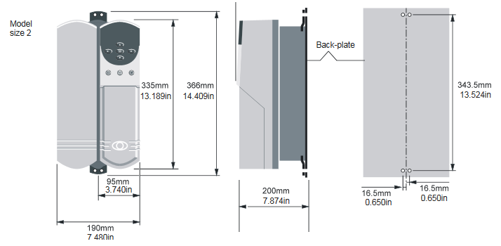
The Control Techniques UNI2403 Unidrive is a size 2 Unidrive with 5.5kW, 10HP, a 25A output and 19.8A input. The versatile Unidrive was the first universal AC drive capable of providing V/Hz, open, and closed loop vector, servo, and regen control in every unit. The unidrive combines all five of these AC drive technologies into one for the ease of the customer.
For quick setup of basic applications, the UNI2403‘s most common parameters are arrange in one main menu. There are hundreds of user-configurable functions that are separated into 20 logicial menus which provides quick setup for advanced apps.
For more info you can email sales@mroelectric.com or call 1-800-691-8511. All of our Control Techniques products are available on our website.
The Schneider Electric Modicon 140CPU53414B CPU is one of the main CPUs of the Quantum Series. It is no long in production from Schneider, but we do still have new and refurbished units available. To make sure this is the CPU is the one for your system we have the notes and overview below.
Overview
– The 140CPU53414B is functionally identical to the non-B version, however the following must be considered:
– If you are using the CPU in a hot standby system, you must use either two non-A versions, two A versions, or two B versions. – The B version required a new flash exec.
– The B version, A version, and non-A flash execs are not interchangeable.
– Schneider software (Concept, ProWorx, and Modsoft) supports the B version.
CPU Module – The following shows the 140CPU53414B CPU module and its components
The following table shows the specifications for the 140CPU53414B CPU
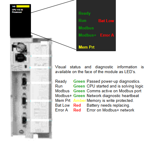
The following figure shows the LED indicators
The following table shows the run LED error codes for the 140CPU53414B
For more info about the 140CPU53414B along with the other Quantum CPUs we carry you can visit our site here. To get a quote you can email sales@mroelectric.com or call 1-800-691-8511.
X171: Terminal NS1–NS2 (coil circuit of the internal line supply– and pre–charging contactor):
– is used to electrically isolate from the line supply (signal contact, terminals 111–213 must be interrogated)
– may only be switched if terminal 48 is open–circuit
terminal 48: Start
– has the highest priority
– Sequence: Pre–charging ON interrogation VDClinkw310V and VDClinkw√2*Vsupply–50V
> 500ms pre–charging contactor OUT, interrogation whether OUT, main contactor IN
>1s internal enable signals (for I/R and module group)
– saved during pre–charging
terminal 63: Pulse enable
– has the highest priority for pulse enable of all the modules
– acts instantaneously (without delay)
Terminal 64: Drive enable
– acts instantaneously on all modules
– when the signal is withdrawn, nset is set to 0 for all drives, and
> for main spindle drive / induction motor module 611 A, the pulses are canceled
after a speed, which can be set, is fallen below. The drive is braked along the ramp.
> for feed drives 611 A, after the selected timer stages have expired (as supplied: 240ms) all of the controllers and pulses are inhibited. The drive brakes along the current limit.
> for 611D drives, the pulses are deleted after a selectable speed has been fallen below and/or a time which can be set, has expired. The drive brakes along the set limits. (For spindles, a ramp can be achieved via regenerative limiting [kW])
terminal 112: Setting–up operation (Vmin3–ph. 24V AC or 34 V DC)
– the VDClink
– closed–loop control is inhibited
– regenerative feedback is not possible, i.e. when braking, VDClink can be >600V!
– this function is interrogated with the start inhibit signal, terminal AS1–AS2.
terminals AS1–AS2: start inhibit signal
– terminals AS1–AS2 closed means ”start inhibit is effective” (setting–up operation) terminals 111, 113, 213: signal contact, internal line contactor
– terminals 111 – 113: NO contact
– terminals 111 – 213: NC contact
terminal 19: FR–:
– reference ground, enable voltage
– floating (connected to the general reference ground, terminal 15 via 10kΩ)
– it is not permissible to connect terminal 19 with terminal 15 (connect to PE rail or X131)
terminal 9: FR+:
– 24V enable voltage
– max. load capability of the power supply:500mA (corresponds to 8 slots;1 optocoupler input
requires 12mA)
X 141: electronic voltages:
– terminal 7: P24 +20.4 to 28.8V / 50mA
– terminal 45: P15 +15V / 10mA
– terminal 44: N15 –15V / 10mA
– terminal 10: N24 –20.4 to 28.8V / 50mA
– terminal 15: M 0V
– it is not permissible to connect terminal 15 to PE (ground loop)
– it is not permissible to connect terminal 15 with terminal 19 (short–circuit via reactor, which internally connects terminal 15 with X131)
terminal L1–L2 for 80kW and 120kW – I/R
– is used to supply the coil of the internal line contactor
– is supplied directly at the line supply with 2–ph. 400V AC (not between I/R and reactor)
– fuse: INw4 A, type gLFan connection for 80 and 120kW I/R
– 3–ph. 360 to 510V AC , 45–65 Hz directly at the line supply (not between the I/R and reactor)
– observe the rotating field (phase sequence)!
– fuse: INw1.5 A (motor protection circuit–breaker)
– conductor connection with additional connection of the power supply at the DC link
– for this operating mode, terminals 2U1, 2V1 and 2W1 of the power supply must be supplied with the line supply voltage between the series reactor and I/R, otherwise the power supply will be destroyed! This is also valid for the monitoring modules!
The Modicon Quantum PLCs provide well-balanced CPUs able to provide leading performance from boolean to floating-point instruction.
Unity Pro programming software supports five IEC languages as standard: IEC Ladder (LD), Structured Text (ST), Function Block Diagram (FBD), Sequential Function Chart (SFC), and Instructional List (IL), as well as the Modicon LL984 language to facilitate installed base upgrades.
High-level multitasking system
Memory capacity up to 7 Mb using Personal Computer Memory Card International Association(PCMCIA) extensions.
Specially designed for process control applications with conformal coated modules and an extensive catalogue of partner modules
Safety processors and I/O modules to manage Safety Instrumented Systems (SIS).
Plug & Play high-performance Hot-Standby solutions with LCD keypad for local monitoring
Adheres to open standards for communications including Ethernet Modbus® TCP/IP, EtherNet/IP (the new ODVA standard for EtherNet/IP™ incorporates Modbus TCP/IP), Profibus and others.
Numerous built-in ports (USB port, Ethernet TCP/IP port with Web server, Modbus Plus and at least one Modbus serial port) on the front panel
In-rack connectivity to Profibus® DP
Embedded Ethernet Router
Increase the availability of your architecture by using Quantum Ethernet I/O modules (QEIO) that support deterministic Remote I/O (RIO)
The Modicon X80 I/O expands your architecture and easily integrates your distributed devices in the same network (such as HMI, variable speed drives, I/O islands…)
Supports the Highway Addressable Remote Transducer (HART), the protocol for sending and receiving digital information across analog wires between smart devices and a control or monitoring system
Choose performance
Offering a large range of processors, Modicon Quantum is ideal for complex processes. The power of its processors results in optimum cycle times, while integrating even more communication functions, diagnostics, memory flexibility and data storage. The Quantum Safety system is now available, certified by TÜV Rheinland, simple to use and ready to be integrated in your automated system.
More flexibility Choose the best topology, daisy chain loop, ring, star, bus… for the design of your Ethernet architecture.
Higher availability Hot-standby CPUs and daisy chain loop topology improve the availability of your process. In the event that the cable is broken, the recovery time is less than 50 ms for an entire Quantum Ethernet I/O architecture.