High Medium Low Voltage

Understanding low, medium, and high voltage is considered to be crucial knowledge in industrial automation.  Not only does this knowledge facilitate a safer environment, but also promotes efficiency and functionality within the working systems.  Here is a breakdown that covers the differences in voltages, the safety aspect, and how knowing about them proves important in the field of industrial automation.

Read more: High Medium Low Voltage

What is Voltage?

Voltage refers to the force that moves electric charges through a conductor. It’s a fundamental aspect of electrical systems, crucial for powering devices and transmitting electricity across various distances. Industries categorize voltage levels into high, medium, and low based on their magnitude and the applications they serve.

  • Low Voltage (LV): Up to 1,000V
  • Medium Voltage (MV): 1,000V to 35,000V
  • High Voltage (HV): Above 35,000V

Low voltage is commonly used in residential and commercial settings, while medium voltage is used in power distribution systems, and high voltage is essential for transmitting electricity over long distances.

Low Voltage

Generally, low voltage refers to voltages below 1000 volts (V). Common examples include household outlets in many countries operating at 120V or 230V. Additionally, low-voltage systems might involve voltages as low as 12V or 24V used in electronics, small appliances, and LED lighting.  

Low-voltage systems are prevalent in everyday devices and smaller-scale electrical applications. They power household electronics, chargers, small motors, and many portable devices. Low voltage remains relatively safe for direct human contact. Furthermore, it remains widely used in residential, commercial, and industrial settings due to its lower risk of electrical hazards.

While low voltage is generally safer to handle, improper handling or faulty wiring can still pose risks of electrical shock or fire hazards, necessitating proper installation and adherence to safety standards.

Medium Voltage

Medium voltage typically ranges from 1000 volts to 35,000 volts. This level of voltage is commonly used in industrial settings, power distribution systems, and larger facilities.

It plays a crucial role in power distribution. They transport electricity from power stations to transformers, which then step down the voltage for use in commercial and residential areas. Medium voltage powers heavy machinery, large motors, and equipment in industries, hospitals, data centers, and universities.

Medium-voltage systems require specialized equipment and trained personnel for installation, maintenance, and operation due to increased risks of electrical accidents. Safety protocols, protective gear, and comprehensive training are essential for handling and working with medium-voltage systems.

High Voltage

High voltage refers to voltages exceeding 35,000 volts and can extend to extremely high levels used in power transmission lines, reaching hundreds of kilovolts (kV) or even megavolts (MV) in some cases.

High-voltage systems primarily serve the transmission of electricity over long distances. Power generated at plants is stepped up to very high voltages for efficient transmission across power lines. High-voltage systems are crucial for delivering electricity from power plants to substations, where it is then stepped down to medium or low voltage for distribution to end-users.

Working with high-voltage systems requires rigorous safety measures, specialized equipment, and highly trained personnel. The risks associated with high-voltage systems are significantly higher, including severe electrical shock, arc flashes, and other potentially fatal accidents.

Reasons to Know the Difference

Workplace Safety

In industrial or commercial settings, where medium or high voltage systems are common, employees must be well-versed in safety protocols specific to each voltage level. Proper training, understanding of safety procedures, and equipment usage reduce the risk of accidents, ensuring a safer work environment

.

Efficiency and Integrity

Each voltage level serves specific purposes within an electrical system. Low voltage is suitable for smaller-scale applications, while medium voltage is crucial for efficient power distribution across larger areas. High voltage is indispensable for long-distance power transmission. Understanding these distinctions ensures that the right voltage is used for the intended application, optimizing efficiency.

Mismatching voltage levels or using incorrect equipment can compromise the integrity of electrical systems. Understanding the correct voltage requirements helps prevent equipment damage, system failures, and electrical fires, ensuring the longevity and reliability of the electrical infrastructure.

Compliance and Standards

Proficiency in handling different voltage levels is often a prerequisite for certifications and licensing in electrical work. Electricians, engineers, and technicians must demonstrate knowledge and competence in dealing with specific voltage levels to obtain the necessary credentials.

Emergencies

During emergencies such as electrical faults, fires, or accidents involving electrical systems, responders need to quickly identify and manage the voltage level involved. Knowledge about the voltage level enables them to take appropriate actions to mitigate risks and ensure a safe resolution of the situation.

Conclusion

In essence, knowledge of the differences between high, medium, and low voltage levels is foundational for maintaining safety, ensuring efficiency, complying with regulations, and responding to emergencies. It stands as the pinnacle standard for safe and efficient utilization of electrical power across various domains. This ranges from everyday household electronics to large-scale industrial infrastructure.

Troubleshooting Fanuc Power Supplies: A Comprehensive Guide

Power supplies are the lifeblood of any industrial automation system, and Fanuc power supplies are no exception. These critical components ensure that your machines receive a stable and reliable source of electrical power, enabling them to function efficiently and accurately. However, like any other electronic equipment, Fanuc power supplies can encounter issues that disrupt production and lead to costly downtime. In this comprehensive guide, we will delve into the world of troubleshooting Fanuc power supplies, equipping you with the knowledge and tools to identify and resolve common problems effectively.

Fanuc A06B-6140-H015 Power Supply

Understanding Fanuc Power Supplies

Before we dive into troubleshooting, it’s crucial to have a basic understanding of Fanuc power supplies. These units are responsible for converting the incoming electrical power (typically AC voltage) into the required DC voltage to operate various components within a CNC (Computer Numerical Control) system. They play a pivotal role in ensuring that the control system, servomotors, and other machine components receive the right voltage and current for smooth operation.

Common Issues with Fanuc Power Supplies

Fanuc power supplies are robust and reliable, but they can still experience problems over time. Here are some common issues you might encounter:

  1. No Power Output: The power supply fails to provide any output voltage, resulting in a complete machine shutdown.
  2. Voltage Fluctuations: The output voltage fluctuates, leading to erratic machine behavior and potential damage to sensitive components.
  3. Overheating: Excessive heat generation within the power supply can lead to thermal shutdowns or even permanent damage.
  4. Fuse Blown: Frequent blowing of fuses can indicate a problem within the power supply or an overload in the connected equipment.
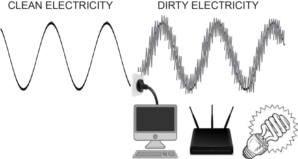
  5. Noise and Interference: Poorly filtered power supplies can introduce electrical noise into the system, causing erratic operation or sensor errors.
  6. Inadequate Output: The power supply might not provide enough current for the connected devices, leading to operational issues.
Read More

Understanding the Varied Roles of Voltmeters and Multimeters in Electrical Measurements

In the realm of electrical measurements, two fundamental tools stand out: voltmeters and multimeters. While both instruments are used to measure voltage, they serve distinct purposes and offer unique features that cater to different needs. In this comprehensive blog post, we will delve deep into the differences between voltmeters and multimeters, shedding light on their individual strengths, applications, and how they contribute to efficient electrical testing and troubleshooting.

Voltmeters: The Voltage Measurement Specialists

Voltmeters are specialized instruments designed primarily for the measurement of voltage, which is the potential difference between two points in an electrical circuit. They come in various forms, including analog and digital voltmeters, and serve a critical role in electrical engineering, electronics, and physics experiments.

Analog Voltmeters: Analog voltmeters provide continuous voltage readings through a pointer on a scale, making them ideal for applications where precise values are not required. They offer excellent sensitivity and are often used in laboratory setups for experimental work. However, their limitations lie in accuracy, as reading analog scales can introduce parallax errors.

Voltmeter

Digital Voltmeters: Digital voltmeters, on the other hand, display voltage readings as numerical values on a digital screen. They are known for their accuracy, precision, and ease of use. Digital voltmeters can measure both AC (Alternating Current) and DC (Direct Current) voltages, making them versatile tools for various applications.

Applications of Voltmeters: Voltmeters are primarily used for:

  • Monitoring power supply voltages.
  • Troubleshooting electrical circuits to detect voltage drops.
  • Measuring voltage levels in electronics and electrical appliances.
  • Analyzing voltage waveforms and harmonics in power systems.
Read More

The Most Widely Believed Myths by Americans

featured image for the survey about commonly believed myths

We’ve all heard them — those myths that stick with you like bubblegum on a hot sidewalk. “Wait 30 minutes after eating to swim,” they say. “Don’t crack your knuckles, or you’ll get arthritis,” warn the cautious. But how many of these long-standing beliefs actually hold water? Spoiler alert: not many.

At MRO Electric, we’re not just about keeping your operations running smoothly but also about setting the record straight. So, we took it upon ourselves to survey Americans to determine which states are most likely to fall for these myths: hook, line, and sinker. 

Are you ready to find out if your state made the list? Or better yet, are you prepared to challenge some of your long-held beliefs? Buckle up, because we’re about to take you on a myth-busting journey across America.

Read More

Demystifying the Magic: How Servo Motors Work

Servo motors are the unsung heroes of the modern technological landscape, silently powering everything from robots and drones to 3D printers and CNC machines. These miniature marvels are responsible for precise control and motion, making them indispensable in various industries. In this comprehensive guide, we’ll demystify the magic behind servo motors, explaining their operation, applications, and the intricate engineering that allows them to work their wonders.

Introduction to Servo Motors

At first glance, a servo motor may appear to be a simple, compact device. Still, beneath its unassuming exterior lies a sophisticated piece of engineering that combines precision, feedback control systems, and electrical circuits to deliver highly accurate rotational motion.

Fanuc Servo Motor Internal Parts

A servo motor typically consists of four main components:

  1. Motor: The heart of the servo, this component generates mechanical motion when electricity is applied.
  2. Feedback system: A sensor (usually a potentiometer or an encoder) that continuously monitors the motor’s position, allowing for real-time adjustments.
  3. Control circuit: The brain of the servo, responsible for processing feedback data and determining the required motor movement.
  4. Output shaft: This shaft extends from the motor and connects to the equipment or mechanism that requires precise motion.

Now, let’s dive into the inner workings of servo motors.

Read More

The Evolution of PLCs in Industrial Automation: A 2,000-Year Journey

Industrial automation has undergone a remarkable transformation over the decades, and at the heart of this evolution lies the Programmable Logic Controller, or PLC. In this comprehensive exploration, we will delve into the fascinating history of PLCs in industrial automation. From their humble beginnings as relay-based control systems to their current status as sophisticated digital control units, we will trace the journey of PLCs through the years, highlighting key milestones, technological advancements, and the profound impact they’ve had on modern industry.

Early PLC System

Chapter 1: The Birth of PLCs

The concept of automation in industrial processes can be traced back to the early 20th century when factories sought ways to improve efficiency and reduce human error. Before PLCs, control systems relied on cumbersome and limited relay logic. It was not until the late 1960s that the first true PLC emerged.

In 1968, a team at Bedford Associates, led by engineer Dick Morley, developed the first PLC, known as the “084.” This revolutionary device aimed to replace traditional hardwired relay systems with a digital alternative. The 084 was a significant departure from earlier control mechanisms, introducing the concept of programming controllers through software, marking a turning point in industrial automation.

Chapter 2: PLCs in the 20th Century

Throughout the 20th century, PLCs underwent significant advancements and refinements. Microprocessor technology, which was rapidly evolving at the time, played a pivotal role in the development of PLCs.

The 1970s saw the emergence of major PLC manufacturers, including Allen-Bradley, Siemens, and Mitsubishi, who introduced their own versions of programmable controllers. These manufacturers began producing PLCs with increased processing power and expanded memory, enabling them to handle more complex tasks and accommodate a broader range of applications.

In the 1980s, PLCs started integrating communication capabilities, such as serial and Ethernet communication. This allowed PLCs to communicate with other devices and systems, paving the way for more extensive automation networks and remote monitoring.

Read More

The Coding Languages of Industrial Automation

Over the decades the communication between operator and machine has been the driving force behind efficiency and safety. Without this crucial communication, manufacturers would come across a plethora of wasted cost as well as dangers situations. Giving precise commands and execute them instantaneously is crucial to making sure any automation facility operates at its best. PLC languages are very important, for their ability to allow the operator to communicate complex tasks to machines. Not only that, but their ability to automate tasks takes allows the operator to focus on other important tasks.
There exist a multitude of challenges that come with performing these tasks with a diverse scenario of situations. Because of this, there are multiple coding languages that become involved when discussing PLCs.

Read more: The Coding Languages of Industrial Automation

Traditional PLC Languages

Ladder Logic (LD)

The OG of programmable languages, Ladder Logic was created by Modicon Corporation in the 1970s for their PLCs. The industry needed a programming language that could effectively mimic the wiring diagrams used in relay-based control systems. These systems were prevalent in industrial settings for controlling machinery and processes.

Ladder Logic’s graphical representation consists of horizontal lines (rungs) with vertical lines (rung rails) that represent control circuits. This is much like the rungs on a ladder. The visual resemblance to electrical wiring diagrams made it intuitive for personnel accustomed to working with relay logic. This eased the transition from hard-wired systems to programmable control.

Today, Ladder Logic’s simplicity and visual nature makes it a fundamental programming language in industrial automation.

Structured Text (ST)

For intricate algorithms and mathematical operations within industrial automation, Structured Text emerges as a prevalent choice. Resembling high-level languages like Pascal or C, ST allows engineers to articulate complex control strategies with ease. Its readability and versatility make it an ideal choice for implementing algorithms in industrial settings.

Function Block Diagram (FBD)

Employing a graphical approach, Function Block Diagrams break down complex systems into interconnected blocks. This visual representation simplifies the design and maintenance of systems, facilitating easy comprehension and troubleshooting in industrial environments.

Sequential Function Chart (SFC)

In scenarios requiring a structured approach to depict sequential operations, Sequential Function Charts come into play. This graphical language represents a sequence of operations in a state-based manner. It offers a clear depiction of complex processes and control flow.

Instruction List (IL)

Instruction List, akin to assembly language, operates at a low level using mnemonic codes. Ideal for detailed control in PLCs, IL enables engineers to create precise instructions for control systems, making it indispensable for fine-tuning operations.

C/C++

C++ became integrated into industrial automation and PLC during the late 90s and early 00’s. However, C++ was slow to be integrated due to lack of optimization to work in a real time setting. Another factor for its slow adoptions, was compatibility. At the time languages like Ladder Logic and Function Block Diagram were more widely used in industry. However, C++ made up for this early setback with its ability to compute complex tasks.

Future Languages

Python and Java

The advent of Python and Java in industrial automation signifies a shift toward versatility and broader system integration. Python’s ease of use, coupled with its capabilities in data analysis, scripting, and interfacing with various systems, has positioned it as an increasingly popular choice. Java, with its platform independence and object-oriented approach, finds a place in larger-scale industrial applications.

The choice of programming language in industrial automation hinges on a multitude of factors, including system requirements, hardware compatibility, existing infrastructure, and the expertise of the programming team. Each language brings its own strengths to the table, catering to different facets of control and automation.

Conclusion

As industries evolve and technology advances, the landscape of programming languages in industrial automation continues to expand. Understanding and leveraging these languages empower engineers to build robust, efficient, and adaptive systems that drive the future of manufacturing and industrial processes.