MagneTek GPD503 Fault Codes

Below is a chart with fault codes regarding the MagneTek G3 GPD503 series drives. MRO Electric and Supply offers free evaluations on units. You can find our RMA form on our repair page. Follow us on Twitter @MROElectric for updates on new products and find any deals we may have.

bbExternal Base Block command
Base Block command at multi-function terminal is active, shutting off GPD 503 output (motor coasting). Temporary condition, cleared when input command is removed.
bUSTransmission error
Control data cannot be received normally for longer than 2 seconds.
CALLCommunication ready
Drive is waiting for the PLC to establish communication.
CPF00Transmission error or control function hardware fault (including internal RAM, external RAM or PROM)
Transmission between GPD 503 and remote operator is not established within 5 seconds after the power supply is turned on. (Displayed on the remote operator.)
CPF01Transmission error
Transmission error occurs 2 seconds or more after transmission has first been established.
CPF02Base block circuit failure
GPD 503 failure.
CPF03NV-RAM (S-RAM) fault
GPD 503 failure.
CPF04NV-RAM (BCC, Access Code)
fault
GPD 503 failure. This fault may be caused after changing EPROM chips. Perform a Sn-03 Reset operation to attempt to clear this fault.
CPF05A/D converter failure in CPU
GPD 503 failure.
CPF06Optional connection failure
Improper installation or wiring of option card.
CPF20A/D converter failure
Defective option card.
CPF21Transmission interface card (option) self-analysis function fault
Defective option card. Check option card connector for proper installation.
CPF22Model code fault
Defective option card. Check option card connector for proper installation.
CPF23Mutual-analysis function fault
Defective option card. Check option card connector for proper installation.
EF (blinking)Simultaneous forward and reverse operation commands
Fwd Run and Rev Run commands are both closed for more than 500 ms. Removing one command will allow drive operation.
EF0External fault
GPD 503 is in Stop mode.
EF3Ext. fault signal at term. 3
A fault condition has occurred in the external circuit(s) monitored by the contact providing input to the indicated terminal. If display is steady, GPD 503 is in Stop mode; if display is blinking, the terminal is programmed to allow continued operation after receiving fault input.
EF5Ext. fault signal at term. 5
A fault condition has occurred in the external circuit(s) monitored by the contact providing input to the indicated terminal. If display is steady, GPD 503 is in Stop mode; if display is blinking, the terminal is programmed to allow continued operation after receiving fault input.
EF6Ext. fault signal at term. 6
A fault condition has occurred in the external circuit(s) monitored by the contact providing input to the indicated terminal. If display is steady, GPD 503 is in Stop mode; if display is blinking, the terminal is programmed to allow continued operation after receiving fault input.
EF7Ext. fault signal at term. 7
A fault condition has occurred in the external circuit(s) monitored by the contact providing input to the indicated terminal. If display is steady, GPD 503 is in Stop mode; if display is blinking, the terminal is programmed to allow continued operation after receiving fault input.
EF8Ext. fault signal at term. 8
A fault condition has occurred in the external circuit(s) monitored by the contact providing input to the indicated terminal. If display is steady, GPD 503 is in Stop mode; if display is blinking, the terminal is programmed to allow continued operation after receiving fault input.
ErrConstant write-in fault
Temporary display, in Program mode, indicating that constant setting was not written into EPROM memory.
FAnCooling fan failure
GPD 503 is in Stop mode.
FUFuse blown
DC Bus fuse has cleared. Check for short circuit in output, and check main circuit transistors.
GFGround fault protection
Ground current > approx. 50% of the GPD 503 rated current.
oCOvercurrent
GPD 503 output current exceeds 200% of GPD 503 rated current, or ground fault has occurred, with ground current exceeding 50% of GPD 503 rated current.
oHHeat sink overheated
Fin temperature exceeds 90° C (194° F)
oH2 (blinking)External overheat
External temperature monitoring circuit(s) detected an overtemperature condition and produced an input signal.
oL1Overload
Thermal motor overload protection has tripped.
oL2Overload
GPD 503 overload protection has tripped.
oL3 (blinking)Overload
GPD 503 output torque exceeds the set Overtorque Detection level, but GPD 503 is programmed for continued operation at overtorque detection.
oL3Overload
GPD 503 output torque exceeds the set Overtorque Detection level, and GPD 503 is programmed for coast to stop at overtorque detection.
oPE01kVA constant setting fault
Sn-01 setting is incorrect.
oPE02Constant setting range fault
An-XX, bn-XX, Cn-XX, or Sn-XX setting range fault.
oPE03Constant set value fault
Sn-15 to -18 (multi-function input) set value fault.
oPE04Constant set value fault
PG constant, number of poles, or PG division rate set incorrectly.
oPE10Constant set value fault
Cn-02 to -08 (V/f data) set incorrectly.
oPE11Constant set value fault
One of the following conditions was detected: • Cn-23 > 5 KHz and Cn-24 5 KHz or • Cn-25 > 6 and Cn-24 > Cn-23
ou (blinking)Overvoltage
Internal monitor of DC Bus voltage indicates that input AC power is excessively high, while GPD 503 is in stopped condition.
ouOvervoltage (OV)
Detection level: Approx. 400V for 230V; Approx. 800V for 460V; Approx. 1000V for 575V.
rrRegenerative transistor Failure
Dynamic Braking resistor has failed.
rHBraking resistor unit overheated
Dynamic Braking resistor has overheated.
Uu (blinking)Low voltage (Power UV)
Internal monitor of DC Bus voltage indicates that input AC power is below Undervoltage detection level, while the GPD 503 is in stopped condition.
Uu1 Low voltage (Power UV)Occurs two seconds after detection of low voltage.
Uu2 Low voltage UVControl circuit voltage levels drop below acceptable levels during operation.
Uu3 Low voltage (MC-ANS fault)Main circuit magnetic contactor does not operate correctly.

Yaskawa P1000 Fault Codes

Below is a table of common fault codes found on Yaskawa P1000 units. If problems continue to occur, it may be worth replacing your unit. MRO Electric specializes in Yaskawa repair, as well as unit distribution, if you are interested in obtaining a new or refurbished P1000 unit.

bATDigital Operator Battery Voltage Low - The digital operator battery is low Replace the digital operator battery.
boLBraking Transistor Overload Fault - The wrong braking resistor is installed Select the correct braking resistor.
bUSOption Communication Error - No signal was received from the PLC. Check for faulty wiring.
CE MEMOBUS/Modbus Communication Error - Faulty communications wiring or an existing short circuit.
CEMEMOBUS/Modbus Communication Error - Faulty communications wiring or an existing short circuit.
CPF02A/D Conversion Error - Control circuit is damaged. Replace the control board or the entire drive.
CPF03Control Board Connection Error - Turn off the power and check the connection between the control board and the drive.
CPF06EEPROM Memory Data Error - Turn off the power and check the connection between the control board and the drive.
CPF07Terminal Board Connection Error - Faulty connection between the terminal board and the control board. Turn off the power and reconnect the terminal board.
CPF08Terminal Board Connection Error - Faulty connection between the terminal board and the control board. Turn off the power and reconnect the terminal board.
CPF11Control Circuit Error - Hardware is damaged. Cycle Power. Replace hardware.
CPF12Control Circuit Error - Hardware is damaged. Cycle Power. Replace hardware.
CPF13Control Circuit Error - Hardware is damaged. Cycle Power. Replace hardware.
CPF14Control Circuit Error - Hardware is damaged. Cycle Power. Replace hardware.
CPF15Control Circuit Error - Hardware is damaged. Cycle Power. Replace hardware.
CPF16Control Circuit Error - Hardware is damaged. Cycle Power. Replace hardware.
CPF17Control Circuit Error - Hardware is damaged. Cycle Power. Replace hardware.Control Circuit Error - Hardware is damaged. Cycle Power. Replace hardware.
CPF18Control Circuit Error - Hardware is damaged. Cycle Power. Replace hardware.
CPF19Control Circuit Error - Hardware is damaged. Cycle Power. Replace hardware.
CPF20Control Circuit Error - Hardware is damaged. Cycle Power. Replace hardware.
CPF21Control Circuit Error - Hardware is damaged. Cycle Power. Replace hardware.
CPF22Hybrid IC Error - Hardware is damaged. Cycle Power. Replace hardware.
CPF23Control Board Connection Error - Hardware is damaged. Cycle Power. Replace hardware.
CPF24Drive Unit Signal Fault - The drive capacity cannot be detected correctly. Cycle Power. Replace hardware.
CPF25Terminal Board Not Connected - Hardware is damaged. Cycle Power. Replace hardware.
CPF26Control Circuit Error - Hardware is damaged. Cycle Power. Replace hardware.
CPF27Control Circuit Error - Hardware is damaged. Cycle Power. Replace hardware.
CPF28Control Circuit Error - Hardware is damaged. Cycle Power. Replace hardware.
CPF29Control Circuit Error - Hardware is damaged. Cycle Power. Replace hardware.
CPF30Control Circuit Error - Hardware is damaged. Cycle Power. Replace hardware.
CPF31Control Circuit Error - Hardware is damaged. Cycle Power. Replace hardware.
CPF32Control Circuit Error - Hardware is damaged. Cycle Power. Replace hardware.
CPF33Control Circuit Error - Hardware is damaged. Cycle Power. Replace hardware.
CPF34Control Circuit Error - Hardware is damaged. Cycle Power. Replace hardware.
CPF35Control Circuit Error - Hardware is damaged. Cycle Power. Replace hardware.
CPF40Control Circuit Error - Hardware is damaged. Cycle Power. Replace hardware.
CPF41Control Circuit Error - Hardware is damaged. Cycle Power. Replace hardware.
CPF42Control Circuit Error - Hardware is damaged. Cycle Power. Replace hardware.
CPF43Control Circuit Error - Hardware is damaged. Cycle Power. Replace hardware.
E5SI-T3 Watchdog Timer Error - Data has not been received from the PLC Execute DISCONNECT or ALM_CLR, then issue a CONNECT command or SYNC_SET command.
EF0Option Card External Fault - An external fault condition is present. Check external causes.
EF1External Fault Terminal S1 - An external fault condition is present. Check external causes. Bad S1 Terminal.
EF2External Fault Terminal S1 - An external fault condition is present. Check external causes. Bad S1 Terminal.
EF3External Fault Terminal S1 - An external fault condition is present. Check external causes. Bad S1 Terminal.
EF4External Fault Terminal S1 - An external fault condition is present. Check external causes. Bad S1 Terminal.
EF5External Fault Terminal S1 - An external fault condition is present. Check external causes. Bad S1 Terminal.
EF6External Fault Terminal S1 - An external fault condition is present. Check external causes. Bad S1 Terminal.
EF7External Fault Terminal S1 - An external fault condition is present. Check external causes. Bad S1 Terminal.
EF8External Fault Terminal S1 - An external fault condition is present. Check external causes. Bad S1 Terminal.
ErrEEPROM Write Error - Noise has corrupted data. Cycle power. Correct the parameter.
FAnInternal Fan Fault - Internal cooling fan has malfunctioned. Check for fan operation.
FbHExcessive PID Feedback - PID feedback input is greater than the level set to. Check parameter.
FbLPID Feedback Loss - Check parameter. There is a problem with the feedback sensor.
GFGround Fault - A current short to ground exceeded 50% of rated current on the output side of the drive. Check motor/cables.
LFOutput Phase Loss - Phase loss on the output side of the drive. Check motor/cables.
LF3Power Unit Output Phase Loss 3 - Phase loss on the output side of the drive. Check motor/cables.
nSENode Setup Error - A terminal assigned to the node setup function closed during run.
oCOvercurrent - Output current greater than the specified overcurrent level. Check parameter. Check motor.
oFA01Option Card Fault - The option card connection is faulty. Check connection. Replace hardware.
oFA03Option Card Fault - The option card connection is faulty. Check connection. Replace hardware.
oFA04Option Card Fault - The option card connection is faulty. Check connection. Replace hardware.
oFA05Option Card Fault - The option card connection is faulty. Check connection. Replace hardware.
oFA06Option Card Fault - The option card connection is faulty. Check connection. Replace hardware.
oFA10Option Card Fault - The option card connection is faulty. Check connection. Replace hardware.
oFA11Option Card Fault - The option card connection is faulty. Check connection. Replace hardware.
oFA12Option Card Connection Error - The option card connection is faulty. Check connection. Replace hardware.
oFA13Option Card Connection Error - The option card connection is faulty. Check connection. Replace hardware.
oFA14Option Card Connection Error - The option card connection is faulty. Check connection. Replace hardware.
oFA15Option Card Connection Error - The option card connection is faulty. Check connection. Replace hardware.
oFA16Option Card Connection Error - The option card connection is faulty. Check connection. Replace hardware.
oFA17Option Card Connection Error - The option card connection is faulty. Check connection. Replace hardware.
oFA30Option Card Connection Error - The option card connection is faulty. Check connection. Replace hardware.
oFA31Option Card Connection Error - The option card connection is faulty. Check connection. Replace hardware.
oFA32Option Card Connection Error - The option card connection is faulty. Check connection. Replace hardware.
oFA33Option Card Connection Error - The option card connection is faulty. Check connection. Replace hardware.
oFA34Option Card Connection Error - The option card connection is faulty. Check connection. Replace hardware.
oFA35Option Card Connection Error - The option card connection is faulty. Check connection. Replace hardware.
oFA36Option Card Connection Error - The option card connection is faulty. Check connection. Replace hardware.
oFA37Option Card Connection Error - The option card connection is faulty. Check connection. Replace hardware.
oFA38Option Card Connection Error - The option card connection is faulty. Check connection. Replace hardware.
oFA39Option Card Connection Error - The option card connection is faulty. Check connection. Replace hardware.
oFA40Option Card Connection Error - The option card connection is faulty. Check connection. Replace hardware.
oFA41Option Card Connection Error - The option card connection is faulty. Check connection. Replace hardware.
oFA42Option Card Connection Error - The option card connection is faulty. Check connection. Replace hardware.
oFA43Option Card Connection Error - The option card connection is faulty. Check connection. Replace hardware.
oFb00Option Card Connection Error - The option card connection is faulty. Check connection. Replace hardware.
oFb01Option Card Error - The option card connection is faulty. Check connection. Replace hardware.
oFb02Option Card Error - The option card connection is faulty. Check connection. Replace hardware.
oFb03Option Card Error - The option card connection is faulty. Check connection. Replace hardware.
oFb11Option Card Error - The option card connection is faulty. Check connection. Replace hardware.
oFb12Option Card Connection Error - The option card connection is faulty. Check connection. Replace hardware.
oFb13Option Card Connection Error - The option card connection is faulty. Check connection. Replace hardware.
oFb14Option Card Connection Error - The option card connection is faulty. Check connection. Replace hardware.
oFb15Option Card Connection Error - The option card connection is faulty. Check connection. Replace hardware.
oFb16Option Card Connection Error - The option card connection is faulty. Check connection. Replace hardware.
oFb17Option Card Connection Error - The option card connection is faulty. Check connection. Replace hardware.
oFC00Option Card Connection Error - The option card connection is faulty. Check connection. Replace hardware.
oFC01Option Card Error - The option card connection is faulty. Check connection. Replace hardware.
oFC02Option Card Error - The option card connection is faulty. Check connection. Replace hardware.
oFC03Option Card Error - The option card connection is faulty. Check connection. Replace hardware.
oFC11Option Card Error - The option card connection is faulty. Check connection. Replace hardware.
oFC12Option Card Connection Error - The option card connection is faulty. Check connection. Replace hardware.
oFC13Option Card Connection Error - The option card connection is faulty. Check connection. Replace hardware.
oFC14Option Card Connection Error - The option card connection is faulty. Check connection. Replace hardware.
oFC15Option Card Connection Error - The option card connection is faulty. Check connection. Replace hardware.
oFC16Option Card Connection Error - The option card connection is faulty. Check connection. Replace hardware.
oFC17Option Card Connection Error - The option card connection is faulty. Check connection. Replace hardware.
oFC50Option Card Error - The option card connection is faulty. Check connection. Replace hardware.
oFC51Option Card Error - The option card connection is faulty. Check connection. Replace hardware.
oFC52Option Card Error - The option card connection is faulty. Check connection. Replace hardware.
oFC53Option Card Error - The option card connection is faulty. Check connection. Replace hardware.
oFC54Option Card Error - The option card connection is faulty. Check connection. Replace hardware.
oFC55Option Card Error - The option card connection is faulty. Check connection. Replace hardware.
oHHeatsink Overheat - Check ambient temperature. Check parameter setting.
oH1Heatsink Overheat - Check ambient temperature. Check parameter setting.
oH4Motor Overheat Fault (PTC input) - Check ambient temperature. Check parameter setting.
oH5Motor Overheat Fault (NTC input) - Check ambient temperature. Check parameter setting.
oL1Motor Overload - Load heavy. Increase accel or decel time.
oL2Drive Overload - Load heavy. Increase accel or decel time.
oL3Overtorque Detection 1 - current has exceeded the value set for torque detection. Check parameter setting.
oL4Overtorque Detection 2 - current has exceeded the value set for torque detection. Check parameter setting.
oL7High Slip Braking oL - Use braking resistor. Reduce decel time.
oPrOperator Connection Fault - The external operator has been disconnected from the drive.
ovOvervoltage - Deceleration time is too short and regenerative energy is flowing from the motor into the drive. Increase decel time.
PFInput Phase Loss - Drive input power has an open phase or has a large imbalance.
rFBraking Resistor Fault - The resistance of the braking resistor is too low.
rHDynamic Braking Resistor - Deceleration time is too short and excessive regenerative energy is flowing back into the drive.
rrDynamic Braking Transistor - The braking transistor is damaged. Cycle power to the drive and check for reoccurrence of the fault.
SCIGBT Short Circuit or Ground Fault - IGBT failure. Cycle power to the drive and check for reoccurrence of the fault.
SErToo Many Speed Search Restarts - Parameters related to Speed Search are set to the wrong values.
TdETime Data Error - An error has occurred in the real-time clock. Replace digital operator.
THoThermistor Disconnect - The thermistor that detects motor temperature has become disconnected.
TIETime Interval Error - An error has occurred in the real-time clock. Replace digital operator.
TIMTime Not Set - Set time in parameter o4-17.
UL3Undertorque Detection 1 - Current is below the minimum set value. Check parameter setting.
UL4Undertorque Detection 2 - Current is below the minimum set value. Check parameter setting.
UL6Motor Underload - Current is below the minimum set value. Check parameter setting.
UnbCCurrent Unbalance - Current flow has become unbalanced. Check for damaged transistors.
Uv1Undervoltage - DC Bus Undervoltage. Check parameter setting. Input phase loss.
Uv2Control Power Supply Undervoltage - Voltage is too low for the control drive input power. Ride-through power loss.
Uv3Soft Charge Circuit Fault - Precharge relay or resistor fault. Bad precharge.
Uv4Gate Drive Board Undervoltage - Voltage drop in the gate drive board circuit. Cycle power to see if fault reoccurs.
voFOutput Voltage Detection Fault - Problem detected with the voltage on the output side of the drive.
vToLVT Overload - The output current of the drive has been elevated for a set length of time.

Encounter a fault code on your Yaskawa P1000 drive?

MRO Electric is here to guide you through the process of identifying and rectifying any issues, with an extensive selection of Yaskawa products and top-tier repair services to choose from.

Yaskawa Drive Types

Yaskawa

Yaskawa Electric is a global manufacturer of high-quality parts used in robotics and automation. They specialize in servos, controllers, switches, robots, drives and more. These parts are used for a variety of purposes in industry. In this post, we will be distinguishing the different types of Yaskawa drives.

CIMR Drives
E7 Drives– Designed for commercial HVAC applications. Embedded with Modbus, APOGEE FLN and Metasys N2.
F7 Drives– Well-rounded drive with a variety of uses. Contains NEMA Type 12 enclosure with space to expand filters, fuses, I/O cards and more.
G7 Drives– Low voltage drive that uses 3 level control to combat problems with long motor cables and premature motor bearing failure. Great vector performance and flexibility. Configured options with pre-engineered cabinet options available.
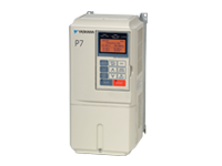
P7 Drives– Created for applications with variable torque like centrifugal pumps and fans.

yaskawa p7

GPD Drives
GPD 333– General purpose AC Drive, 1/4 the size of normal PWM drives.
GPD 503/505/506– High-performance three phase voltage/frequency output with adjustable speed control.
GPD 515– PWM AC drive designed for low motor noise and high starting torque.

Microdrives
J1000 Drives– General purpose drives with open loop voltage/frequency control with preferred parameter feature. Simple variable speed of up to 7.5HP.
V1000 Drives– Compact current vector drive designed for efficiency and maintainability. Capable of up to 25HP. Economical for basic variable speed applications.
V1000-4X Drive- The same as the V1000 but with an enclosure built for dust tight environments.

Other Drives
A1000 Drives – High performance general purpose drive capable of up to 1000HP. Used for general purposes.
P1000 Drives – Torque performance capable of withstanding 1000HP. Oriented towards variable torque applications including centrifugal pumps and fans. Configured and bypass options available.
U1000 Industrial Matrix Drives – Regenerative high performance vector drive capable of up to 800HP. Used for general purposes.

Source: https://www.yaskawa.com/

Visit MRO Electric and Supply’s website to see all of our available Yaskawa Drives. If we don’t have what you need listed on the site, contact us at sales@mroelectric.com or (800) 691-8511 and we will be happy to help!

Yaskawa SIGMA 5 Troubleshooting

Yaskawa has established a firm position as the leading international developer of servo products in recent years, surpassing its competitors with innovation and utilization of advanced modern technologies.

Its Sigma 5 series is absolutely top of the class! Incorporated with the latest and most desirable features, this fleet of servo products does not disappoint. The Sigma 5 series catalog is briefly over-viewed below.

  • SERVOPACKs is a series consisting of high-end networkable amplifiers that support motors up to 55 kW
  • Rotary Servo Motors with outputs in the wide range of 50W – 15kW
  • Direct Drive Servomotors with peak torque 6-600 Nm
  • Linear Servomotors are directly driven by a coil
  • Linear Slides complete the package for customers using linear servomotors, comprising of components such as slides, carriages, etc.

With such a versatile range of products, Sigma 5 series is easily what you would want to have in your workshops and industries.

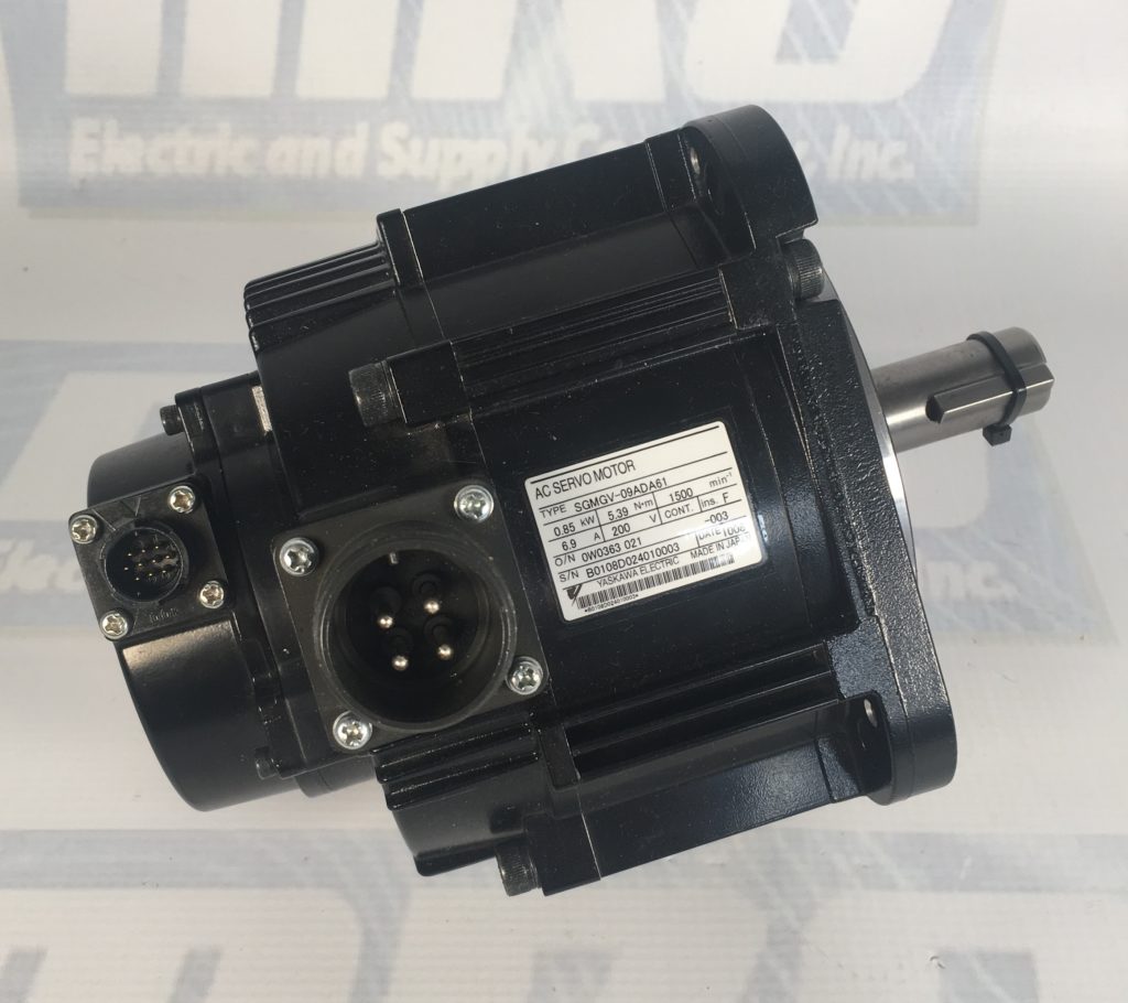
SGMGV-09ADA61

All servo drives are tailored according to contemporary market demands. With so many different kinds of motors, the drives make use of complex algorithms that allow engineers to exercise precise control over the motor output, helping them achieve the accuracy modern applications require.

Yaskawa is highly regarded among consumers and the industry for its professionalism. From product development to customer dealing, this quality shows through at each stage, and this is exactly what puts this company at the top.

This blog is dedicated to one aspect of this characteristic: Troubleshooting. Sigma 5 series is undoubtedly the most functional of all but this also means that the intricacies involved can sometimes be difficult to handle.

If one of these products does not perform as it should be, troubleshooting it should be something that field engineers should be able to do. Thankfully, the Sigma 5 series is accompanied by clear troubleshooting guidelines and is one of the most easy to handle.

  • Product Documentation

Each product comes with comprehensive documentation that can be accessed at any time to gain in-depth knowledge of its working. These documents contain important information like dedicated troubleshooting guides, operating parameter, alarm lists, product structure, and specifications.

With this information at hand, troubleshooting any of the Sigma 5 products becomes a piece of cake!

  • Software Support

Sigma 5 series comes with a very supportive software suite as well which can serve as the perfect troubleshooting tool. During installation and operation, these software used extensively for product setup and configuration.

The SigmaWin+ is an intuitive tool that allows convenient setup of each servo product. If you observe anything out of the normal with your Sigma 5 products, the first thing to do would be to check whether the configuration settings are compatible with your application.

Its most helpful function is the alarm diagnostic function. Troubleshooting is usually initiated after a machine raises an alarm. This software is designed to identify all the possible reasons that might have generated a specific alarm, and presents possible corrective measures as well.

Moreover, SigmaWin+ has enhanced features such as wiring check and auto-tuning of multiple parameters. Using these you can not only find the loopholes you are looking for but also optimize operations.

  • Yaskawa Customer Support

To top off the aforementioned troubleshooting options, MRO’s Repair team is always available for help. If you are experiencing a mind-boggling issue with your Sigma 5 products, this team is the go-to. Apart from repair work, MRO Electric and Supply has a core exchange program that saves the buyer time and money when receiving their new unit.

Motoman Teach Pendants And More

Yaskawa Motoman, an American subsidiary of Yaskawa Electric Corporation, was founded in 1989 and since then have been able to get over 380,000 industrial robots, 10 million servos, and 18 million drives into automation systems around the world. Robots are the wave of the future and Yaskawa Motoman is at the top of this market. Using an automated robotic system in your work space will allow you to free up many other costs and resources that may not have been available before.  The key to efficiency is simplicity and using  Motoman Teach Pendants to give instructions to your robot makes that possible.

Teach Pendants are non-tethered devices that allow your robot to be controlled remotely. These devices are crucial for industrial robotics as they are not only used for assigning operations but they are able to edit commands, emergency stop commands, and even view past operations. Motoman Teach Pendants are split between the older models(ERC, XRC, MRC) and the newer models(DX and NX Series’).

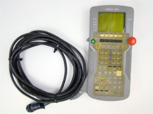
MRC

The older models such as the MRC, which came out in 1994, were able to increase the workload of an industrial robot by up to 300%. This was also the first time ever that a single teach pendant was able to control two robots at the same time. Four years later when the XRC model was released, it was a huge improvement as Motoman was able to add control of more axes and even up its synchronous control of two robots to four industrial robots.

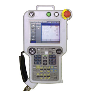
nx100

Later in 2004, the NX series of controllers was released. These devices featured Windows CE with a high-power processor, back-lit color touchscreen, built-in ethernet, and a huge amount of memory. A single teach pendant can control up to 36 axes and 4 separate robots. It’s Advanced Robot Motion control allows for the most accurate results. For information about the DX series, please visit one of our previous blog posts featuring the DX200 controller and Yaskawa’s new ArcWorld project.

Looking inside the ArcWorld 6000 and DX200 Controller

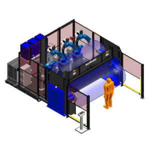
Yaskawa’s ArcWorld 6000 line of robotic welding systems offer the most cost efficient and powerful solution to your welding needs. ArcWorlds are pre-built, easy to install, and ready to run immediately after installation. The units can configured with multiple robots, a heavy duty positioner or servo controlled external axes. The 6000 line can handle payloads from 755 kg to 1255 kg over a 2 or 3 meter span.  There are many other cool benefits to running the ArcWorld over a traditional welding system:

  • All controllers and power sources are installed and shipped on the frame for minimal setup
  • The world class MA1440 arc used for welding can be combined with multiple robots to cut cycle time by 15%
  • Twist locking connectors for all cabling
  • Fully compliant with most recent robot safety standards (ANSI/RIA R15.06-2012)
  • A standard workcell is only documented and supported by Yaskawa Motoman

arcworld 6000

The RM2-Series Positioners are are powered with three AC servo motor drives and have a payload capacity of 1555 on each side. With a 6.5 second rapid indexing time, the positioners have a part length between 3000mm and 3500mm. Convenient slip ring built for  the fixture of utilites such as Ethernet and DeviceNet. The positioner uses MotoMount mounting technology inside of the Yaskawa ArcWorld Unit.

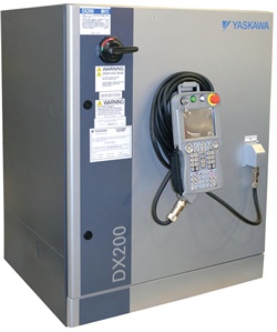
Typically used inside of the ArcWorld 6000 line is the DX200 controller. These controllers can coordinate motion between 8 robots with up to 72 axes. Its Advanced Robot Motion control gives the ArcWorld unit the ability to use the arc’s at their peak performance with pinpoint precision. DX200 controllers are available with Cat 3 Functional Safety Unit. Maintenance is hardly necessary as these controllers efficiently use energy and use top of the line prevention methods for most types of failures. Contact Yaskawa Motoman right now to inquiry on price options for different ArcWorld models and make your automation system perform at its best.

dx200

Yaskawa V1000

Yaskawa V1000 – Compact Vector Control Drive

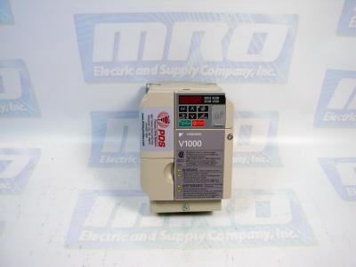
The Yaskawa V1000 is a compact current vector drive with dual microprocessor logic. There are 3 primary models: 200V 3-Phase Input, 200V Single-Phase Input, and 400V 3-Phase Input.  It is possible to run the drive without connecting the digital I/O wiring.

It is important when installing Yaskawa V1000 drives that proper electrostatic discharge (ESD) procedures are taken. Failure to comply could result in an ESD discharge that could damage the drive circuitry. If the drive is being operated at low speeds, the cooling effects are diminished and motor temperatures can increase which can lead to overheating. Continuously operating an oil-lubricated motor in the low speed range may result in burning.

A dynamic braking resistor can be used with the V1000 series. Dynamic braking helps bring the motor to a smooth and rapid stop when it is working with loads of high inertia. As the drive lowers the frequency of a motor with high inertia connected, regeneration occurs. This can cause over-voltage when the regenerative energy flows back into the DC bus capacitors. A braking resistor can help prevent these overload errors from occurring.

The drive functions are devided into 2 primary groups that are accessible through the Yaskawa V1000’s digital LED operator. Drive mode allows for motor operation and parameter monitoring. Parameter settings cannot be changed when functions are accessed in drive mode. However, alarm information and history can be accessed in drive mode. Programming mode allows access to the setup. There you can adjust and verify drive parameters as well as Auto-Tuning. The drive will not allow motor operation changes such as start and stop when the LED is accessing a function Programming mode. The V1000 is set to Drive mode when it is first powered up. The Up and Down arrow keys can be used to switch displays.

MRO Electric and Supply carried new and refurbished Yaskawa V1000 Drives. For more information or to request a quote, call 800-691-8511 or email sales@mroelectric.com.

Yaskawa V1000
Yaskawa V1000