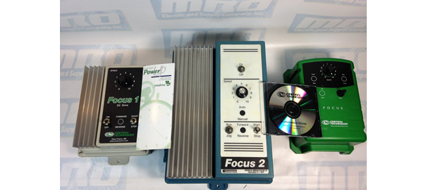
Focus 1, 2, 3 Drives

AC Drives vs DC Drives: Which is best for you?

What is an electric drive?

An electric drive is used to control the motion and speed of motors, robots and/or other electrical devices. Usually, a drive will have one or several electric motors. In the modern day, any control offered by these devices is often aided by software, which can help control accuracy. There are two main types of electric drives: AC drives and DC drives.  

What is an AC drive?

An AC drive stands for Alternating Current, but could also be referred to as an adjustable speed drive, adjustable frequency drive, variable frequency drive, variable speed drive, frequency converter, inverters and a power converter. Typically, they are used to control the speed of an electric motor in order to enhance the operation of numerous applications relying on electric motors, minimize mechanical stress on motor control applications, generate energy as efficiently as possible, cut down on energy usage and, lastly, optimize process control.

Also known as adjustable speed drives, inverters and power converters, adjustable frequency drives, and variable speed drives, AC drives are similar to  DC drives because an AC input is regulated to DC by simple bridge rectifiers, commonly referred to as SCRs. Because AC drives use a capacitor bank to stabilize and smooth this DC voltage, the DC output would be half cycle according to AC input phase frequency. Then, power is supplied to the motor in the output section of the drive by means of 6 output transistor or IGBT modules. Essentially, the AC input current is converted by the drive to DC and, again, converted back to AC in order to supply the motor. The current is converted twice by the drive because the AC input is either 50 or 60-hertz cycles. When the DC voltage is converted to AC again by the drive, it uses a carrier frequency of at least 2 KHZ to 100 KHZ in more complex drives. Therefore, the output current is able to be raised tens or hundreds of times without burning up the motor coil with an AC drive.

The AC motor is also able to rapidly switch speeds with zero problems because of this function. AC drives typically have numerous types of feedbacks from simple, 2-line incremental encoders, to resolvers or absolute encoders with a significant resolution that facilitates the drive to calculate motor shaft speed and angle as spot-on as possible. There is a third circuit called regeneration on a handful of larger, more powerful drives. This circuit converts the inertia of the load and motor to AC power and transfers it back to the input lines when the motor transitions from a significantly high speed to a low one, which, in the long run, would conserve on power and increase energy efficiency.

AC drives serve many different industrial and commercial applications.

What is a DC drive?

Essentially, a DC drive converts an AC drive into direct current, otherwise known as DC to operate a DC motor. The majority of DC drives use a handful of thyristors (also known as SCR’s) to craft a half cycle of DC output from a single phase AC input, also known as the half-bridge method. The more complex ones use up to 6 SCR’s to power a DC output from a 3 phase AC input, which is known as the full-bridge. Therefore, in the full-bridge method, we have 2 SCR’s for every input phase. The aspects of a DC drive are as follows: compact in size, outstanding speed regulation, broad speed range, cost-effective for medium and high HP applications, and speed changes that are derived from by increasing or decreasing the amount of DC voltage the drive feeds the motor.

Controlled by the gate input, an SCR switch is similar to a one direction switch and turns on by applying a low voltage to the gates. The drive can control the motor speed by applying the voltage to the gate at a contrasting angle of the input phase. To authenticate the motor speed and compensate if necessary, the majority of DC drives require the motor to have a tachometer as means of feedback. A tachometer is essentially a mini permanent magnet DC motor accompanied by the main motor’s shaft.

Because higher motor speed generates more voltage in the tachometer, the drive references this voltage to ensure the motor is operating at a correct speed per-user settings. More compact DC motors have a permanent magnet field while larger DC motors have a separate coil inside the motor, also known as a field, which eliminates the need for a permanent magnet in the motor. DC drives with field output typically have a more compact circuit to supply the field coil. DC drives are best used in when a DC motor exists in a safe and dry atmosphere and the use of DPG, DPG-FV, TENV, or TEFC motor enclosures is required, motor speeds are able to reach 2500 RPM, application requirements are medium or large, and starting torque is either unpredictable or greater than 150%.

What’s the difference between AC and DC drives?

When it comes to AC drives vs DC drives, DC drives are commonly considered problematic, despite their prestige for having simple circuits, providing high start-up torque, and being ideal for applications with constant speed due to the requirement of commutators and brush assemblies in their motors. These motors can become worn over time, have operational issues, and will likely require labor to preserve.

On the opposite side of the spectrum, AC drives are considered more energy-friendly and are able to endure rapid speed changes more efficiently due to their running induction motors. Often times, they have hundreds of numerous programmable parameters for secure protection. Although, because of these factors, the AC drive is more complex, modernized software is simplifying their overall use.

In previous years, DC drives were regularly utilized due to their simplicity, the majority of machine manufacturers prefer to use AC drives as of late. The complexity of an AC drive has been repeatedly simplified and fine-tuned, resulting in a plethora of advantages.

Though in the past DC drives were often utilized due to their simplicity, most machine manufacturers now prefer to use AC drives (especially for servo applications). The intricacy of an AC drive has been simplified over time and has many upper hands.

Conclusion

So which would work better for you? When it comes to AC drives vs DC drives, it’s important to keep in mind DC drives’ infamous ability to provide high start-up torque, which makes them ideal for applications that have a constant speed. In comparison, AC drives are generally more energy efficient. They also have running induction motors, and can therefore handle rapid speed changes better than DC drives. 

Interested in purchasing an AC motor or a DC motor? Check out our inventory here. Curious to learn more about electric motors and devices? Check out our blog. Having a question or request? Feel free to contact us.
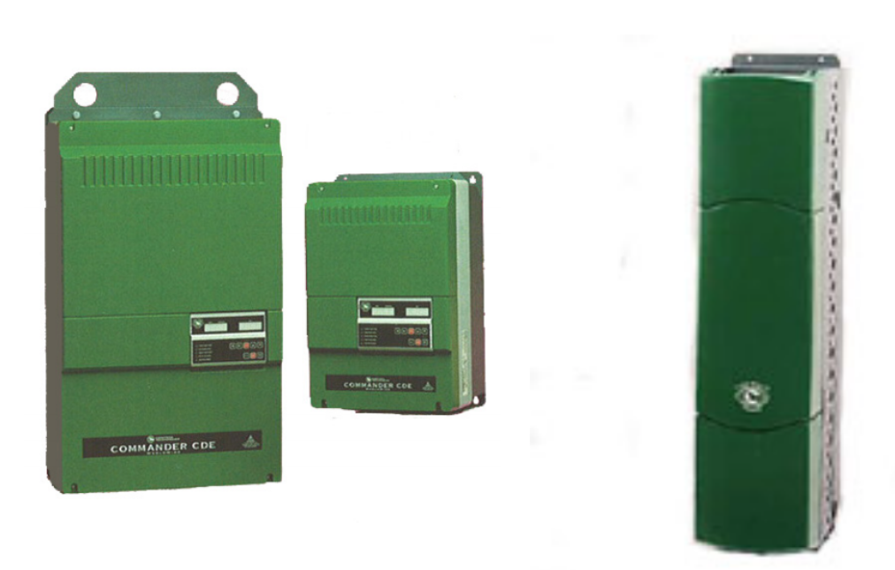
Control Techniques Commander CDE Trips: Troubleshooting

CDE TRIPS ( MEDIUM / LARGE AND HPCDE )

Control Techniques Commander CDE Trips: Troubleshooting

MRO Electric and Supply has new and refurbished Control Techniques parts available now, and also offers repair pricing. For more information, please call 800-691-8511 or email sales@mroelectric.com.

Control Techniques Commander CDE Trips: Troubleshooting

When a failure occurs with the CDE drive the display will flash a series of segment characters for the trip.

Example: tr iP OU

Commander CDE series stores the past ten failure codes in parameters #10.14 – 10.23 in trip number form. A numeric value trip code is a basic form of the symptom for the technician to work with. These past trips can be accessed via the keypad by entering the value of 149 in the keypad at parameter 00.

Scroll to menu 10, for parameter #10.14 to see a trip number.

Example: 6

Symptom explanations provide an avenue on how to analyze the drive for particular problems.

To make the troubleshooting process easier a chart was created to link the type of trip with the symptom.

TRIP Display | TRIP Number | Symptom

cL 114-20m Loop of current loop 1
Et2External trip contact has opened
I . t3Overload lxt- Sustained Overcurrent
Oh4Heatsink over temperature- Fan Failure ???
OI AC5Instantaneous AC over current trip
OU6DC bus over voltage-Braking Resistor Problem
Ph7AC Supply phase loss
PS8Internal power supply fault
th9Motor thermistor trip-Hot Motor
OI dC10Instantaneous DC over current trip
EPS11External power supply fault +24vdc short?
th512Motor thermistor short circuit
UU13DC bus under voltage
SCL14Serial comms. Loss-Keypad loose/failure
POdL15Loss of Control keypad
cL2164-20mA Loop Loss of current loop 2
cL3174-20mA Loop Loss of current loop 3
EEF18EEPROM
Prc219Processor 2 fault
OA20Ambient over temperature
rS21Stator resistance measurement failure
OUSP22Overspeed Trip
hFPP26-39Hardware Fault
PhPC100AC Supply phase loss from a drive module
OtPC101Over temperature trip in a Drive module
OtPn102-109Over temperature trip in Drive Module #n
PSPn110-117Over voltage trip in Drive Module #n
I OPn118-125Instantaneous Over current in Drive #n
OuPn126-133Over voltage trip in Drive Module #n
dcPn134-141Instantaneous DC current trip in Drive #n
FtYP142Spurious Unidentified trip
ConF143Module Address switches incorrect
8.8.8.8.-I x t trip Warning flashing dots

Emerson Industrial Automation Unidrive SP

Emerson Industrial Automation: Unidrive SP Troubleshooting

Emerson Industrial Automation: Unidrive SP Troubleshooting

Updated August 2019: Click here to view Unidrive fault codes.

DIGITAL INPUTS

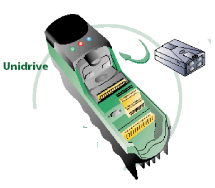
The Unidrive SP can be enabled to run in several ways. The drive can use digital inputs, keypad, or a field buss networks to give the OK to run. The drive will display inh, rdy, or run depending on the given commands. The drive can be programmed to use positive or negative logic. The logic type is set up at #8.29 in the Control Techniques Unidrive SP. The Unidrive SP defaults to positive logic. When the drive is in positive logic you will need to inject +24VDC to activate the digital inputs. The +24VDC can be supplied by the drive or externally.

The Unidrive SP can be enabled to run in numerous ways.

When the drive is in the terminal mode the following sequence occurs under default conditions:

Unidrive SP:

Inh = Drive disabled = Connect pins 22-31 drive should go to rdy
Rdy = Drive enabled = Connect pins 22-26 drive should go to run
Run = Drive is enabled and ready to run when a speed reference is applied

Parameter #0.05 sets up the Reference Select. This will tell the drive where to search for run commands and speed references. You will only need to close the enable signal if it is set to pad. Then, the keypad can be used to control the drive and to set the speed reference. The speed reference will come in on an analog input if you choose a terminal code. The digital inputs will select the enable, run, and preset selections. The drive should operate as seen above if the digital inputs are activated correctly.

DRIVE SEQUENCER

When the drive is not running, there are several additional parameters in menu 6 that can assess the issue. The digital inputs may be configured wrong or inactive if the parameters are not going to a 1 with the corresponding commands. Check the following parameters:

#6.15 = 1 = Drive enabled

#6.43 = 1 = Control word disabled, Set to 1 for Field Buss Control

#6.29 = 1 = Hardware Enable (Pin 31 is activated)

#6.30 = 1 = Run Forward #6.31 = 1 = Jog

#6.32 = 1 = Run Reverse

#6.33 = 1 = Forward/Reverse

#6.34 = 1 = Run

#6.37 = 1 = Jog Reverse

#6.39 = 1 = Not Stop

Unidrive SP

The voltage on the corresponding digital inputs should be measured if the parameters in menu 6 aren’t changing state accordingly. The DC voltage should change between 0VDC and 24VDC when a command is given. Check the digital input configuration in menu 8 if menu 6 isn’t changing and the voltage is.

CONTROL WORD

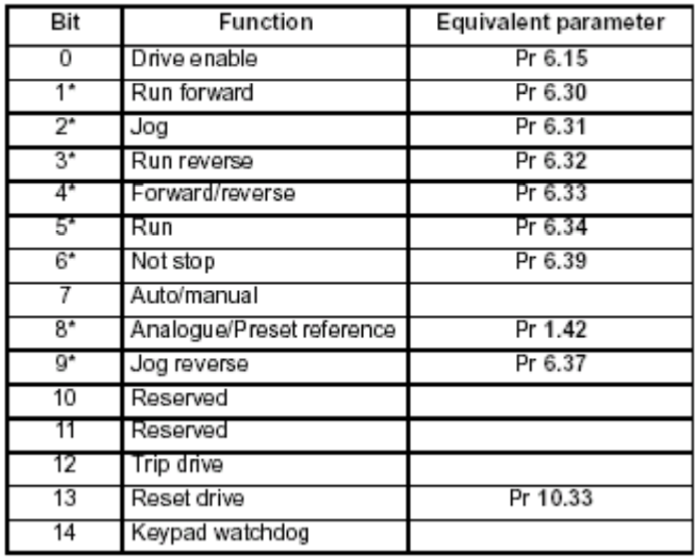
To control the start/stop functions, the drive does not have to use the digital inputs. When #6.43 = 1 the control word is enabled. The drive will now accept a decimal value from 0 to 32767 at #6.42. This decimal value can be converted to a binary value.To see the function that will be carried out, you can reference the binary value to the chart below.

Unidrive SP

Speed Reference

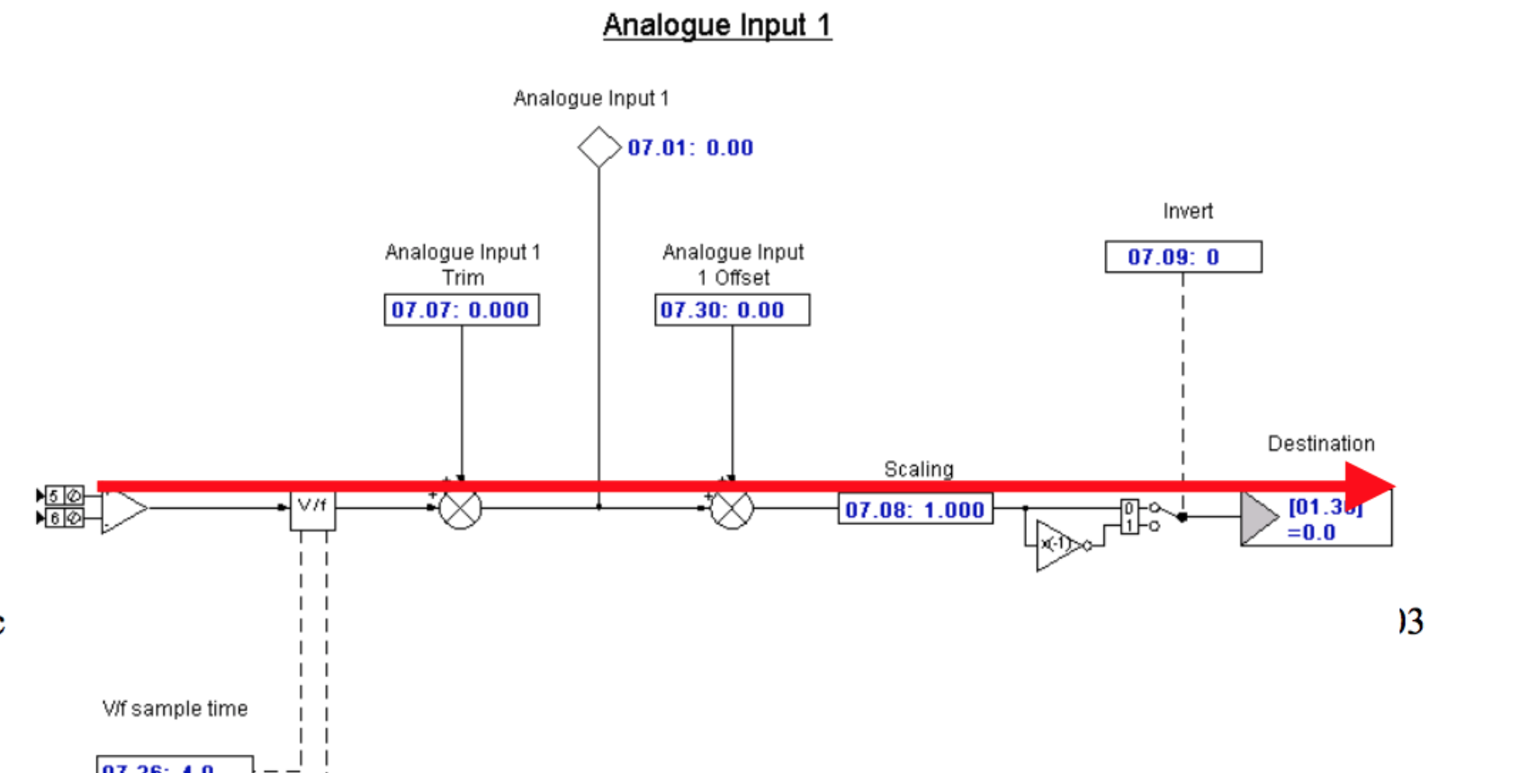
The drive still may not run if the digital inputs and the drive sequencer are each working properly. There could be an issue with the speed reference to the drive if the display shows Run but the motor isn’t turning. The speed reference is able to be applied in several methods. An analog input can be used (current or voltage), preset speeds, and a field buss reference. The example is a 0-10VDC signal on analog input #1.

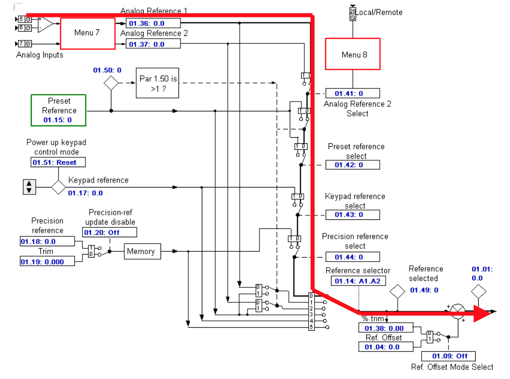
The final speed of the demand is parameter #3.01. The speed reference should be displayed here if the digital inputs and the drive sequencer are failing to operate properly. Check menu 1 and 2 to determine where it is stopping if the reference is not getting to this point.

If the drive is running in torque mode, the torque reference will come on parameter #4.08 under default conditions. #4.08 is able to be linked to an analog input or be written to via a filed buss network.

Unidrive SP

#7.01 should be inspected to determine if it changes with the change in reference at terminal 5 once the signal has been confirmed. #7.01 goes from +/- 0% – 100%. Check the destination of the speed reference at #7.10 if everything looks good. Follow it to the destination and confirm the speed reference value is arriving there and then through #3.01.

Unidrive SP

Contact the America’s Service Center if the drive will still not run after the Speed Reference, Digital Inputs and Drive Sequencer have all been confirmed.

MRO Electric and Supply has new and refurbished Control Techniques Unidrives available now, and also offers repair pricing. For more information, please call 800-691-8511 or email sales@mroelectric.com.

Emerson Industrial Automation: Unidrive Classic HF Trip Codes

Emerson Industrial Automation: Unidrive Classic HF Trip Codes
This document is pertinent to all Unidrive Classic models
MRO Electric and Supply has new and refurbished Control Techniques Unidrives  available now, along with our other Control Techniques products. Contact us about pricing for repairs. For more information, please call 800-691-8511 or email sales@mroelectric.com.
Emerson Industrial Automation: Unidrive Classic HF Trip Codes

HF81 Software Error (odd address word)

Unidrive Fault Code DiagnosticsHF81 HF82 HF83 HF84 HF85 HF86 HF87 HF88 HF89 HF90 HF91 HF92 HF93 HF94 HF95 HF96 HF97 HF98 HF99

HF82 Large Option Module Missing

HF83 Power Board Code Failure

HF84 Current Offset Trim Failure

HF85 A to D failure (ES-CC step)

HF86 Interrupt Watchdog failure

HF87 Internal ROM check error

HF88 Watchdog Failure

HF89 Unused Interrupts (nmi as source)

HF90 Stack Overflow

HF91 Stack Underflow

HF92 Software Error (undefined op code)

HF93 Software Error (protection fault)

HF94 Software Error (odd address word)

HF95 Software Error (odd address instruction)

HF96 Software Error (illegal ext bus)

HF97 Level 1 Noise

HF98 Interrupt Crash

HF99 Level 1 Crash

HF Faults are not recorded in the Drive Historical Fault Log

All of the above HF trips in BLUE are typically a result of some sort of hardware failure on the UD90A control PCB. This control board is common to all Unidrive Classics.

For the HF codes in RED refer to the following page

HF82 Large option module missing

If one of the UD7x large option modules is removed, the trip may be expected. There is an issue with either the large option module or the UD90A control PCB if this trip occurs at any other time than the case above.

HF83 Power Board Code Failure

Because the UD90A control PCB was unable to recognize the power rating of the power PCB it is connected to, this trip occurred.

The trip is likely due to the power PCB in the Drive or a problem with the UD90A control PCB on Unidrive Sizes 1 to 4 (which includes UNI1401, UNI1402, UNI1403, UNI1404, UNI1405, UNI2401, UNI2402, UNI2403, UNI3401, UNI3402, UNI3403, UNI3404, UINI3405, UNI4401, UNI4402, UNI4403, and UNI4404).

UD99 PCB or the UD90A PCB cause the trip on a Unidrive Size 5. The interconnects between the PCBs should also be checked, as they could also cause a trip.

HF84 Current Offset Trim Failure

Due to an issue with the current feedback on the drive, this trip occurs. The trip is likely due to the power PCB in the Drive on Unidrive Sizes 1 to 4. An issue with the UD90A control PCB may also cause this trip.

The UD99 PCB or the UD90A PCB cause the trip on a Unidrive Size 5, along with the interconnects between the PCBs.

HF88 Watchdog Failure

This trip can result from a faulty UD7x Co-Processor. With power off, remove Co-Processor and re-apply power.

HF82 Large option module missing

If one of the UD7x larger option modules is removed while the Drive is powered up, this trip is likely to occur. There is an issue with either the UD90A control PCB or the large option module if this trip were to occur at any other time.

HF83 Power Board Code Failure

The UD90A control PCB was unable to recognize the power rating of the power PCB it is connected to, which is what caused the trip.

The trip is likely due to the power PCB in the Drive on Unidrive Sizes 1 to 4, however, an issue with the UD90A control PCB is also able to cause this trip.

The trip is caused by the UD90A PCB, the UD99 PCB, or the interconnects between the PCBs on a Unidrive Size 5.

HF84 Current Offset Trim Failure

If there is an issue with the current feedback on the Drive, this trip will occur. The trip is likely due to the power PCB in the Drive, but an issue with the UD90A control PCB could also result in a trip on Unidrive Sizes 1 to 4.

On a Unidrive Size 5, the trip is cause by either UD99 PCB or the UD90A PCB. The interconnects between the PCBs could also cause this trip and should be checked.

A trip could be caused by either UD99 PCB, UD90A PCB, or the interconnects between the PCBs on a Unidrive Size 5.

HF88 Watchdog Failure

A faulty UD7x Co-Processor and large option module, ( includes UD70, UD71, UD73, UD74, UD75, and UD76) can cause this trip. Remove Co-Processor and re-apply power with power off.

Unidrive Fault Code DiagnosticsHF81 HF82 HF83 HF84 HF85 HF86 HF87 HF88 HF89 HF90 HF91 HF92 HF93 HF94 HF95 HF96 HF97 HF98 HF99

Schneider Electric / Modicon PLC and HMI Batteries

Schneider Electric / Modicon PLC and HMI Batteries

MRO Electric and Supply has new and refurbished Schneider Electric and Modicon Quantum parts available now, and also offers repair pricing. For more information, please call 800-691-8511 or email sales@mroelectric.com.

Schneider Electric / Modicon PLC and HMI Batteries

Product Line Model Type Part Number Manufacturer
140CPUxxxxx
Lithium 3V
990XCP98000
Duracell (DL2/3A)
(soldered connector)
Quantum 140XCP90000 Lithium 990XCP99000
Quantum
141MMS42501
Lithium 3V
990XCP98000 or Duracell (DL2/3A)
43502625 (soldered connector)
Quantum
141MMS53502
Lithium 3V
990XCP98000 or Duracell (DL2/3A)
43502625 (soldered connector)
Compact PC-O984-xxx Lithium 3.6V (long) “O” 60-0576-000 Eternacell (T04/41)
Compact
PC-A984-1xx
Lithium 3.6V (short) “A”
60-0576-100
Saft (LS3)
PC-E984-2xx Maxell (ER3STC)
Momentum
172xNN2xx2
Lithium 3.6V
170XTS15000
Tadiran (TL-5955)
PNN PV:03
JNN PV:01
Momentum 172xNN2xxx2 Alkaline “AAA” Commercially Available
110CPUx1x0x
Lithium 110XCP98000 Duracel (DL2/3A)
Capacitor 110XCP99000 (soldered connector)
Modicon 984 AM-C986-003
(2 cell pack)
MA-9255-000
Modicon 984 AM-C986-004
Modicon 984 AM-M907-1xx
Modicon 984 AM-M909-0xx
Modicon 984 AM-C921-xxx 60-0490-000
Modicon 984 PC-L984-x8x
Lithium 3.6V “AA”
60-0515-000
Eternacell (T06141)
Modicon 984 PC-O984-x8x Maxell (ERGC#5)
Modicon 984 PC-E984-x8x Saft (LS6)
Modicon 984 PC-O984-455 Tadaran (TL-5104)
Modicon 984 PC-O984-351
Modicon 984 AM-C986-004
Modicon 984 AM-C996-80x
Modicon 984 PC-M984-23x
Modicon 984 AS-B984-1xx
Modicon 984 AM-S929-00x
Lithium
MA-8234-000
Modicon 984 AS-B885-00x
Modicon 984 AM-O984-ATX 60-0490-000
Modicon 984 Rechargeable (Qty. 2) 60-0610-000
Modicon 984 100-865 (Qty. 3) 60-0595-000
Modicon 984 AM-O984-MCX 60-0582-000
Modicon 884
Modicon 884
AS-884A-xxx
MA-8234-000
AS-J890-x0x
Modicon 584 AS-506P-xxx Lithium (3 card) MA-0147-001
Modicon 584 AS-509P-xxx Lithium (4 card) MA-0147-002
Modicon 584 AS-M507-00x 60-0481-000
Modicon 584
3 Card Battery Pack
Lithium AS-5284-001
Alkaline AS-5284-002
Modicon 584
4 Card Battery Pack
Lithium AS-5378-002
Alkaline AS-5378-001
Modicon 484
Lithium MA-0147-001
Alkaline 60-0286-000
Modbus Multiplexer
Modbus Multiplexer NW-0278-000 60-0549-000
0085/0185 (Sharp)
0085/0185 (Sharp)
(with connector) PA-0254-000 Sharp
(without connector) PA-0493-000 (UBATN-5001-SCZZ)
Symax
Symax
Model 400
Lithium 3.6V “AA”
60-0515-000 Eternacell (T06141)
Model 450 29576-03688 Maxell (ERGC#5)
Model 600 (SqD Part #) Saft (LS6)
Model 650 Tadaran (TL-5104)
PS25
PS35
8052 MCM713
Symax
PS20/21
Alkaline “D”
Commercially Available
PS30/31
PS50/51
PS60/61
Symax
8005 Model 50
Ram Memory Pack
8005 MP1
8005 MP4
Symax
PS20
Battery Holder
29904-08200
(SqD Part#)
Symax
SCP1xx 8020 SMM115
8040 PCM-110 (SqD Part #)
Symax
M100
29904-08960
(SqD Part #)
Symax
8009 Compact
Lithium 3V (Type BA1)
Sanyo (CR12600SE)
TDI Battery Co. (?)
Otte Controls
(DUNT-521NCZZ)
Symax
Symax 20
8884 SBP20
(SqD Part #)
PanelMate
PanelMate
all models
60-0627-000
Maxell
60-0628-000
PanelMate PM0632400 (Qty. 3) 60-0595-000
PanelMate PA-0285-000
PanelMate MA-024M-000
Telemecanique
TSX Premium TSXP57xxx Lithium 3.6V “1/2 AA” TSXPLP01 Saft (LS3)
TSX Micro TSXP37xxx Single TSXPLP101 Maxell (ER3STC)
TSX Micro Ten Pack
TSX Micro
TSXMRPxxxxx
Lithium 3V “Button” TSXBATM01
Panasonic (BR2325)
Single TSXBATM101
10 Pack
CCX17
TCCX17xxx
Lithium 3.6V “1/2 AA” TSXPLP01 Saft (LS3)
Single TSXPLP101 Maxell (ER3STC)
Ten Pack
FTX117
TFTXRSMxxxxx
Lithium 3V “Button” TSXBATM01
Panasonic (BR2325)
Single TSXBATM101
10 Pack
TSX 17
Lithium 3.6V “1/2 AA”
TSX17ACC1
Saft (LS3)
Maxell (ER3STC)
(Soldered Connectors)
XBTKN
Lithium 3.6V “1/2 AA”
TSX17ACC1
Saft (LS3)
XBTKM Maxell (ER3STC)
(Soldered Connectors)
Series 7
TSX 27xx
2.6 V
AZ1 AQ 0006
2.4 Volt with minimum of 110 mAH
TSX P471x/P472x Shrink-wrapped cells
TSX RAM xx 8 Soldered on board
TSX AXM 162
TSX AXM 171xx/182
TSX SCM 2xxx
UC TSX 27
Series 7
TSX P473xx/P474xx 3.6V
AZ1 AQ 0002
3.6 Volt with minum of 110 mAH
TSX P67xxx Shrink-wrapped cells
TSX 76 x Soldered on board
TSX P871/P872/P874xx
TSX P76 x
TSX P107xxx
TPMX P474xx
TPMX P674xx
TPMX874xx
TPMX P1074xx
TSX T407 x
TSX RAM xxx 16
TSX MEM 4x
TSX P87 30/310 3.6V (Qty. 3)

FANUC A16B-1212-0100 Power Supply Unit

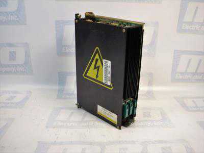
MRO Electric and Supply has new and refurbished FANUC A16B-1212-0100 power supply units available now, and also offers repair pricing. For more information, please call 800-691-8511 or email sales@mroelectric.com.
a16b-1212-0100 wiring diagram
A16B-1212-0100 Wiring Diagram

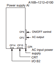
The A16B-1212-0100 is an easy to mount CNC power supply that is designed to connect directly to the System 0 master PCB. All its AC inputs and DC outputs are linked via connectors. Because the power supply unit has a built-in input unit function, it is not necessary to prepare a a separate relay or input unit for switching the AC input on and off. The AC input can be connected directly to the power supply unit. The unit has an AC service outlet, which is switched on and off simultaneously with the power supply unit. This AC service outlet can be used to supply power to a unit such as a fan motor. Sometimes the alternate FANUC part number P007P0355 is used.

FANUC A16B-1212-0100 Input / Output Connectors

Connector NameDescription
CP1200/220/230/240 VAC input
CP2200/220/230/240 VAC output
(switched on and off simultaneously with the power supply unit)
CP3- Power on/off switch contact signal input.
- External alarm signal input.
- Alarm signal input.
CP12- Supply of +5 V, +15 V, –15 V, +24 V, and +24E to the master
printed–circuit board.
- EN signal output.
CP14- +24E supply for the additional I/O B2 printed circuit board
(for Series 0).
- +24E supply for the connection unit (for Series 15)
CP15+24V supply for the 9” monochrome CRT/MDI unit (for Series 0).

* MRO Electric can offer replacement 9" monitors for your unit.

Descriptions of the A16B-1212-0100 I/O Signals and Display LEDs
    1. AC power supply display LED (green) – When an AC power source is connected to the power supply unit, the LED lights regardless of whether the unit is on or off.
    1. Alarm display LED (red) – If the power supply unit is switched off because of an alarm condition due to a failure such as an output error, the alarm display LED lights and remains on until the alarm condition is cleared by pressing the OFF switch or shutting down the AC power supply.
  1. ENABLE signal EN (output) – This TTL level signal indicates that all DC outputs are normal. It becomes low if an output failure is detected in any circuit.
  2. Power supply on/off control signal ON–OFF–COM (input) – If two switches are connected to this circuit as shown below, pressing the ON switch turns on the power supply unit, while pressing the OFF switch turns the unit off. If an alarm occurs in the power supply unit, and the alarm display LED lights in red, however, pressing the ON switch will not turn on the power supply unit. In this case, it is necessary to remove the cause of the alarm and press the OFF switch. Pressing the OFF switch clears the alarm condition. Subsequently pressing the ON switch turns on the power supply
    unit.
  3. External alarm signal AL (input) – When a contact signal from another unit or external power supply becomes ”closed,” the ENABLE signal of this power supply unit becomes low, thus immediately turning off the power supply unit.
  4. Alarm signal FA–FB (output) –  This contact signal indicates the state of all DC outputs. The contact is open when all the DC outputs are normal. It is closed if an output failure is detected in any DC output circuit. If an external alarm signal (item 5) is connected, the FA–FB contact opens, when all DC outputs are normal and the external alarm signal is ”open.” The contact closes when the external alarm signal becomes ”closed.”
Adjustments and Settings

The FANUC A16B-1212-0100 power supply unit requires no adjustment or setting. Do not attempt to adjust the reference voltage (=10.00V) at A10 unless absolutely necessary, because the reference voltage has been adjusted during unit test; merely confirm the voltage across A10 and A0 of check connector CP16. If the reference voltage at A10 falls outside the rated range, set it to 10.00V, using VR11, while measuring the voltage with a digital voltmeter. Rotating VR11 clockwise increases the voltage at A10. After the power supply unit is replaced, always to check the reference voltage at A10.

a16b-1212-0100
A16B-1212-0100
fanuc repair

Automation Cleanup Procedures for Flood Damages in TX & LA

Automation Cleanup Procedures for Flood Damages in TX & LA

MRO Electric is determined to provide the best service and support to businesses affected by Hurricane Harvey during these difficult times as they resume operation and employees get back to work.

Water-immersed electronic devices and motors in automation systems need appropriate treatment after flood water subsides. We have compiled information we learned from our past flood relief activities below, which we think our customers affected by Harvey may find useful.

We also have the capability to wash and test the amplifiers and printed circuit boards at our repair facilities.

Recovering Industrial Electronics from Flood Damage

If the CNC and related equipment are treated properly after being soaked with flood water, it is possible to reduce or even recover from the damage. The purpose of this section is to describe proper post-flood treatment.

Things to keep in mind:

  • In case of flood, do not open cabinets and units. It is better to wait until the flood water recedes.
  • If it is possible to drain actively, the early drainage can reduce the damage.

Outline of the procedure after flood water recedes is as follows:

  1. Remove batteries & cables
  2. Wash the units
  3. Dry the units
  4. Check the insulation resistance
  5. Check the functionality (Performed by MRO Electric’s engineers)

Remove batteries & cables

In order to minimize a damage to unit, please perform following at first:

  1. Please remove battery cables from units and PCBs (Printed Circuit Board) as soon as possible. Flooded batteries may cause rust damage to PCB’s circuitry and could result in irreparable PCB damage. Removing the batteries will result in loss of CNC data, but it is necessary to protect the hardware from further damage.
  2. Remove cables before washing. Please properly tag or mark so you will be able to connect cables back correctly.

Washing the Units

Wash the units according to the procedure below as soon as possible. Damage will worsen if washing is delayed.

  1. Unit –  Floodwater often contains contaminates such as dirt and oil. This could stick to the unit and could become difficult to remove. Use a neutral detergent, such as multipurpose kitchen detergent, tap water, and nylon brush (do not use a metal brush) to clean them as much as possible. Use a small brush such as a toothbrush and clean the entire unit with specific attention to connectors and sockets.
  2. Relays –  If relays have water inside, please open the case and clean inside. (If the case cannot be opened, you will need to replace it.)
  3. Transformers –  It is not possible to clean inside a transformer coil, however, please clean the unit as much as possible especially around the electrical terminals.
  4. Cables –  Connector housings will contain flood water. Please disassemble the connectors to drain any water, clean them, and then dry by hanging the cable with the connector at the bottom. (It is also possible that flood water also enters between cable strands). Please be mindful of this.
  5. Servo and Spindle Motors – These motors cannot be disassembled by the customer.
    Please have MRO Electric’s engineers clean these parts. If you see waters entering inside the cover on the motor, the cover may be removed to release the water and carefully clean around the feedback assembly.
  6. Motor Drive Units – Please use flowing water to clean the motor drive units. Please refrain from submerging the unit during cleaning.

Drying Units

After washing, please remove as much water as possible and let then dry. The electrical resistance is lower due to the moisture, so please do not attempt to mount or apply electrical power until the unit is completely dry. It will take a long time if you just leave the unit at room temperature. Transformers, especially, will require a few months if not dried to high temperature. It is necessary to use a high heat to evaporate the humidity inside the transformer.

Drying Oven
It is possible to gain enough insulation back in a few hours if you can use a drying oven with enough high heat. However, please be careful if the temperature is too high, it may melt the insulation material. A vacuum type drying oven may be useful for this type of equipment.

Here are a few examples of temperature and drying time for FANUC products, after removing as much water as possible by hand:
· Servo Transformer – In 120 degree C (248 degrees F) for 8 hours
· Servo Motors – In 80 degree C (176 degrees F) for 12 hours (with Pulse coder removed)
· PCB (Printed Circuit Boards) – In 60 degree C (140 degrees F) for 1 hour.

Without a Drying Oven
Please prepare a fanned heater. It is a good idea to use a hair dryer to send heated air (around 140 degrees F is desirable). Please be careful as it may become too hot if you send the air directly to the unit. PCB and units may be dried in a half, to one full day, but the transformer may take a few days.

Check the Insulation Resistance

It is very important that insulation resistance is tested before applying power.

  1. Transformer – Measure the insulation resistance using 500V Megameter between coils, and between coil and metals such as core. The measurement should be 10 Megohm or more.
  2. Servo Motors and Spindle Motors – Measure the insulation resistance between the motor windings and ground. The measurement should be 10 Megohm or more. Please note that the encoders may be damaged by the flood water. Please open the motor case and check. If you see the sign of entering the water, the encoders may need to be replaced.

Check the Functionality

MRO Electric engineers and machine tool builder engineers may need to work in sync because machine side repair and adjustment will also be required. If the insulation resistance is adequate, then the unit may be installed. Confirm all cable connections and wiring, then apply power and confirm the operation. If insulation is not sufficiently recovered due to insufficient drying, there is a possibility of ignition due to short circuit or heat generation, so pay attention to the generation of smell and smoke for a while after energization, immediately turn off the power when there is an abnormality.

If parameters were lost and a recent back up is not readily available, it is our recommendation to contact the machine tool builder to assist you. They will also be able to assist in any machine side adjustments and/or set up procedures before the final operation is started.

Our goal is to quickly and safely return your machine back into production. Do not hesitate to contact MRO Electric if you believe your equipment is damaged and is in need of testing and/or repair, or if you require a replacement part.

Please contact us at 800-691-8511 or at sales@mroelectric.com.