Yaskawa CIMR-AU4A0038FAA A1000 Drive – Product Spotlight

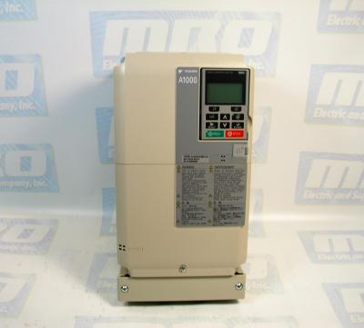
The CIMR-AU4A0038FAA is a three-phase 400 Volt AC Drive. There are two modes on this AC drive – Programming Mode and Drive Mode. In Drive Mode, the user can operate the motor and observe U monitor parameters. Parameter settings cannot be changed or edited while in Drive Mode. In Programming Mode, the user can edit and verify parameter settings and perform Auto-Tuning. When the drive is in Programming Mode, it will not accept a Run command unless b1-08 is set to 1. If b1-08 is set to 0, the drive will only accept a Run command in Drive Mode. After editing the parameters, the user must exit the Programming Mode and enter Drive Mode before operating the motor.

Check out our website for all of our Yaskawa products!

Local mode is when the drive is set to accept the Run command from the digital operator RUN key. Remote mode is when the drive can be set to accept the Run command from an external device, such as input terminals or serial communications. Switch the operation between Local and Remote using the LO/RE key on the digital operator or via a digital input. After selecting local, the LO/RE light will remain lit. The CIMR-AU4A0038FAA will not allow the user to switch between Local and Remote during run.

Several Application Presets are available to facilitate setting up the drive for commonly used applications. Selecting one of these presets automatically assigns functions to the input and output terminals and sets a predefined number of parameters to values appropriate for the selected application. An Application Preset can either be selected from the Application Selection menu in the Setup Group or in parameter A1-06. The default parameter setting is 0, which disables the presets. The following setting ranges are listed below:
– 0: Disabled
– 1: Water supply pump
– 2: Conveyor
– 3: Exhaust fan
– 4: HVAC
– 5: Compressor

MRO Electric and Supply stocks a variety of A1000 Drives including the CIMR-AU4A0038FAA. For more information or to request a quote, please email sales@mroelectric.com or call 800-691-8511.

CIMR-AU4A0038FAA
CIMR-AU4A0038FAA
HMIGTO5310

Magelis HMIGTO5310 Touch Panel – Product Spotlight

The HMIGTO5310 (HMI-GTO-5310) is a Modicon Magelis GTO advanced touchscreen panel. It features a 10.4 inch display with a 96 MB flash memory. The panel uses an external power supply of 24 Volts DC, and has a lithium battery for internal RAM. It’s back light lifespan is 50,000 hours at 25 °C. Using an SDHC or SD card, one can add up to 32 GB of data storage to the HMIGTO5310. It also has an internal RAM of 512 kB used to back up data. Using either the panel’s software or its touch panels, a user can control 16 different levels of screen brightness.

The HMIGTO5310 weights precisely 2 kg. It measures 272.5 x 214.5 x 57 mm (W x H x D).  The HMIGTO5310 can be mounted by using 4 screw clamps with flush mounting.

The HMIGTO5310 supports a large number of downloadable protocols, including the Modbus TCP, Siemens Simatic, Rockwell Automation / Allen Bradley, Omron Sysmac, Mitsubish Melsec, FIPWAY, Modbus Plus, Uni-TE, and Modbus. The panel supports a number of integrated connection types, some of which include the Ethernet RJ45, the USB 2.0 ports, COM2 serial links, and a COM1 serial link.  When using the COM2 serial interface, be aware that the serial port is not isolated. The signal ground and frame ground terminals are connected inside the panel. There is risk of electric shock if precautions are not taken. When using the signal ground terminal to connect an external device to the panel, verify that a short circuit loop was not created when you set up the system. Connect the #8 signal ground terminal to remote equipment when the host PLC unit is not isolated. Connect the #8 signal ground terminal to a known reliable ground connection to reduce the risk of damaging the circuit.

When setting up RS-485 communication, the cable diagram for some equipment may require polarization on the terminal side. This terminal does not require any special setting as it handles polarization automatically.

MRO Electric and Supply stocks HMIGTO5310 panels. For more information or to request a quote, please contact us at 800-691-8511 or at sales@mroelectric.com.

HMI-STU-855

Modicon Magelis HMI-STU-855 (HMISTU855) Product Spotlight

The Schneider Electric / Modion HMI-STU-855 is a 5.7 inch touch panel screen with a Magelis operating system and CPU ARM9 processor. It uses a QVGA TFT color touchscreen with a pixel resolution of 320 x 240 pixels. It uses an external supply source of 24 volts and consumes 6.8 watts of power. It has 16 MB of application battery with 64 kB available to back up data. The HMISTU855 is able to download a number of protocols including Modbus, Modbus TCP/IP, Uni-TE, and 3rd party protocols.  When using the HMISTU855, all connections to the communication ports on the bottom and sides of the unit must not put large amounts of stress on the ports. Be sure to securely attach communication cables to the panel or cabinet. Use only RJ45 cables with a functioning locking tab.

Critical detected alarm indicators and systematic function require independent and redundant protection hardware or mechanical interlocks. It is important that when power is cycled, the user waits at least 10 seconds before restoring power. Switching the power on and off quickly can damage the unit. The interface is connected to remote equipment using a RS232C or RS-485 cable. The connector that is used is a RJ45-8 pin type. The using a long PLC cable to connect the unit, a difference of electric potential can be observed between the cable and the ground, even when connected to a ground. The serial port on the HMI-STU-855 is not isolated. The signal ground and frame ground terminals are connected inside the unit. When setting up the RS-485 communication, the cable diagram for some equipment may need polarization on the terminal side. This terminal does not need any special setting because it can handle polarization automatically.

MRO Electric and Supply Company stocks many Modicon Magelis HMIs and panels, including the HMI-STU-855. For for information or to request a quote, please email sales@mroelectric.com or call 800-691-8511.

HMI-STU-855
HMI-STU-855

Micromaster 420

Siemens Micromaster 420 Troubleshooting Tips

Often people have difficulty installing a replacement drive that we send out, and normally it just takes the troubleshooting tips from the manual to get them up and running. However, the manual isn’t always the easiest to find or sort through, so below we’re posting the Siemens Micromaster 420 Troubleshooting section from the manual which should help anyone who is working to get the issues with their drive sorted out.

MRO Electric supplies and repairs Micromaster 420 Drives. To request a quote for a repair or spare, please call 800-691-8511 or email sales@mroelectric.com.

Read More

Yaskawa GPD 503 Drives

Installation of Yaskawa GPD 503 Drives:

1. Be certain your input voltage source, motor, and drive name plates are all marked either 230V, 460V, or 575V. Other voltages can be used, but they require additional programming.

2. Mount drive on vertical surface with adequate space for air circulation.

3. Remove front cover, fit conduit to bottom plate, and connect power and ground wires.

Caution: Be certain you connect power to terminals L1, L2, and L3 only, or serious damage will result. Connect motor to T1, T2, and T3 only.


Installation of External Run/Stop Switch and Speed Potentiators:

Important: Complete the Installation and Keypad Operation before attempting external control.

  1. Disconnect power, remove cover, and wait for “CHARGE” light to go out.
  2. Connect a switch to terminals 1 and 11 using two conductor shielded wire. This circuit is 24Vdc, very low current; use a quality rotary or toggle switch (all wire should be 14-18AWG). Connect the shield to terminal 12 on the drive end only.
  3. Install a single conductor “jumper wire” between drive terminals 5 and 11.
  4. Connect a manual speed potentiometer rated 2000-3000 ohms, 1 watt minimum, using three conductor shielded wire, with shield connected at terminal 12. Connect wires to the potentiometer. Trace wire closest to the top and connect to terminal 17. Trace center wire of potentiometer through and connect to terminal 16. The remaining wire will be connected to the trim pot in step 5.
  5. Connect a trim potentiometer rated 2000-3000 ohms, 1 watt minimum, as close to the drive terminals as possible. Viewing the potentiometer from the back, connect a single conductor wire from the left terminal to terminal 15 of the drive. Connect a short jumper wire between the center and left terminals. Connect remaining wire from manual speed pot as shown.
    Check out our other Yaskawa products, including GPD-505 and GPD-506 drives!
    MRO Electric and Supply Company carried new and remanufactured Yaskawa GPD 503 Drives. To place an order or for more information, call 800-691-8511 or email sales@mroelectric.com.

    Yaskawa GPD 503 Drives
    Yaskawa GPD 503 Drives

TSX PLCs – Compact, Flexible, Cost-Effective

TSX PLCs
TSX Nano PLCs are easy to set up and have numerous built in functions, such as memory for storing programs, battery-backed RAM, and real-time clocks for modules with 16 and 24 I/O’s. They can be installed easily on a mounting rail or base plate in the vertical or horizontal position. TSX PLCs are programmed in lists of instructions using the FTX 117 programming terminal, in Ladder or Instruction list language using software on an FT 2000, FTX 517 terminal or PC compatible. They can be used to augment extendable TSX PLCs using a single extension per base. Depending on the model they have

16 I/O : 9 inputs + 7 outputs
24 I/O : 14 inputs +10 outputs.

The following types of inputs and outputs are used:

Inputs : 24 Volts
Outputs : Relay outputs for models with ~ 100… 240 Volt power supply, transistor outputs with positive logic for models with 24 Volt power supply.

I/O Extension

Each TSX Nano base PLC can be extended using an I/O extension. This extension is created by one of the PLCs with 10, 16, or 24 i/o. The function of each PLC is defined by the position of the coding selector switch:
Position 0 : base PLC
Position 1 : I/O extension

Peer PLCs

Up to 3 peer TSX PLCs, communicating via common words, can be connected to the base PLC. In this case, only the base PLC can receieve an I/O extension. The function of each PLC is defined by the position of the coding selector switch. I/O addressing of peer PLCs is identical to that of the base TSX PLC. The extension link cable between the base PLC and PLC extensions is shielded, twisted pair  and is no more than 200 meters long.  Each PLC has 2 reserved (IW) and 2 reserved (QW) words for exchanging data between PLCs. These exchange words are updated automatically. For each PLC, the user program is only able to write to the 2 %QW output words and read the 2 %IW input words.

MRO has many Modicon PLCs available. For more information, please email sales@mroelectric.com or call 1-800-691-8511.

Simodrive 611 Power Modules – Manual Anthologies

Simodrives 611 power modules can be used to operate the following motors: 

  • 1FT6, 1FK6 and 1FK7 servo motors 
  • 1FW6 built–in torque motors (direct drives) 
  • 1FN linear motors 
  • 1PH main spindle motors 
  • Standard induction motors; if IM operation is selected, only inverter pulse frequencies of 4 kHz and 8 kHz are permissible. 
  • 1PM hollowshaft motors for main spindle drives (direct drives) 
  • 1FE1 main spindle motors 
  • 2SP1 motor spindle 
  • Third–party motors, if according to the motor manufacturer the motor meets the requirements for sine modulation, insulation, and dV/dt resistance.

For special motors with a low leakage inductance (where the controller settings are not adequate), it may be necessary to provide a series reactor in the form of a 3–arm iron core reactor (not a Corovac reactor) and/or increase the inverter pulse frequencies of the converter. Motors with a low leakage inductance are, from experience, motors that can achieve high stator frequencies (maximum motor stator frequency > 300 Hz) or motors with a high rated current (rated current > 85 A).

A wide range of 1–axis or 2–axis power modules is available. These modules are graded according to the current ratings and can be supplied with three different cooling techniques. The current–related data refers to the series–preset values. At higher frequencies of the fundamental waves or for higher clock cycle frequencies, ambient temperatures and installation altitudes above 1000 m above sea level, power deratings apply as subsequently listed. Matched, pre–assembled cables are available to connect the motors. Ordering information is provided in the ”Motors” section of the NC 60 catalog. Shield terminal plates are available to meet EMC requirements when using shielded power cables.

The equipment bus cable is included in the scope of supply of the power module. The drive bus cables must be ordered separately for the digital system. The current data of the power modules (PM modules) are normalized values to which all of the control units refer. The output currents can be limited by the control unit being used.

MRO Electric offers both New and Remanufactured Siemens Simodrives 611. Please visit our Siemens CNC and Automation Page for more information. You may also contact sales@mroelectric.com or call 1-800-691-8511.

Siemens Simodrive 611

Siemens Simodrive 611