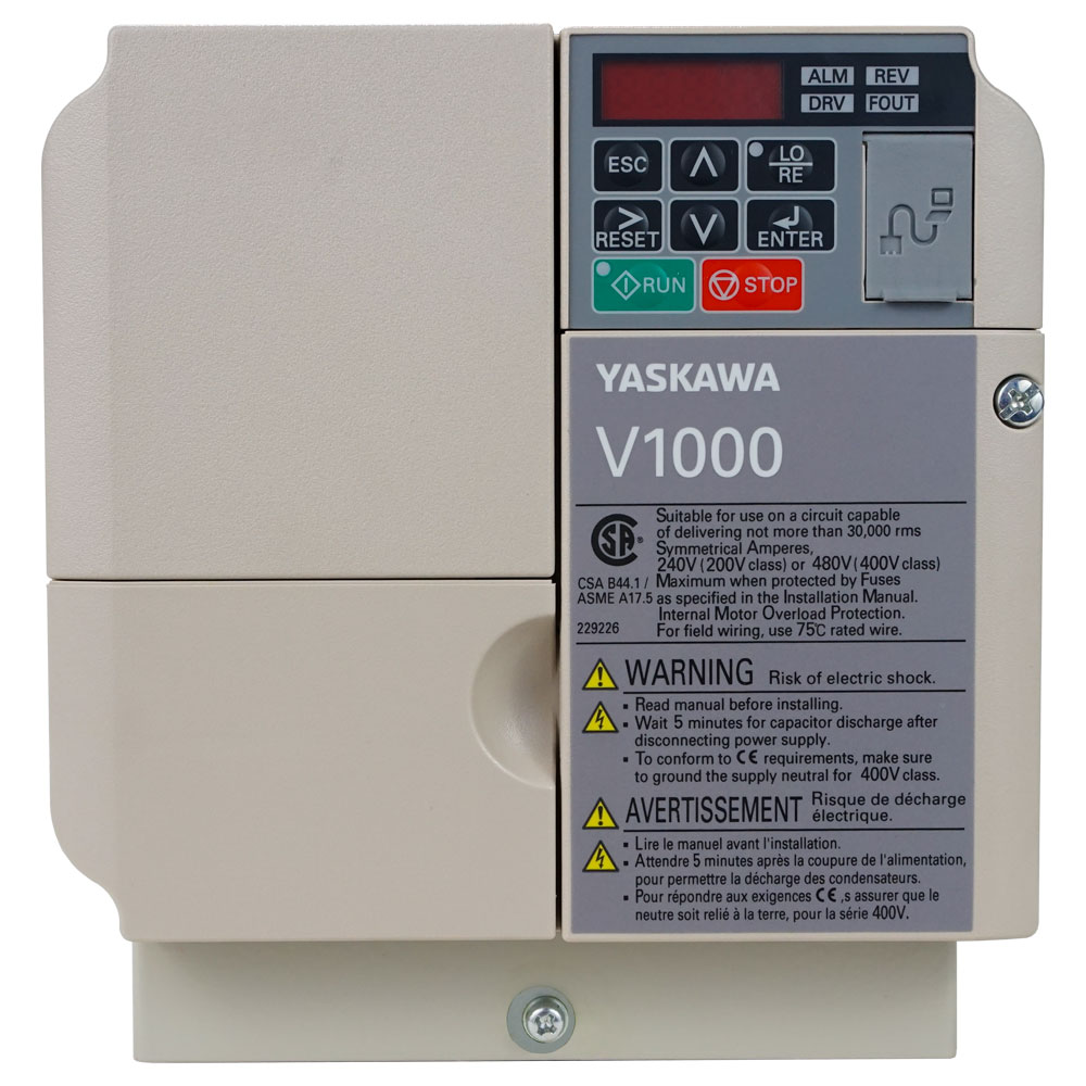
Installing a Control Techniques UNI2403 Drive

The Control Techniques UNI2403 is a robust and versatile variable frequency drive (VFD), part of the renowned UNI series designed for controlling 3-phase AC motors. Its reliability in applications from conveyors and pumps to fans and packaging machinery is well-established. However, like any sophisticated piece of power electronics, its long-term performance and reliability are directly tied to the quality of its installation.

A proper installation is more than just connecting wires; it’s about ensuring safety, optimizing performance, and guaranteeing a long, trouble-free service life. This article outlines the critical best practices for installing your UNI2403 drive.

Read more: Installing a Control Techniques UNI2403 Drive
UNI2403

Pre-Installation

They say a little planning goes a long way. This saying is applicable when it comes to installing drives. Both temperature and location play important factors in trying to figure out where to install your UNI2403. Ideally, you want the drive installed in a cool and ventilated environment to avoid overheating the drive.

Another thing to consider is if the location you’re installing the drive in is easily accessed by contaminates. Try to avoid places that gather large amounts of contaminate like dirt, dust, grime, and grease. Often these contaminates accumulate and build up in the drive overtime which then leads to overheating.

Observe Safety Procedures

Before starting any work, ensure the entire system is electrically isolated. Lock Out, Tag Out (LOTO) the main power supply to prevent accidental re-energization.

After disconnecting power, wait for the specified time (refer to the manual) for the DC bus capacitors to fully discharge. The UNI2403 has a status LED that indicates charge; never rely on this alone—always measure the voltage at the DC bus terminals with a multimeter to confirm it is safe (<50V DC).

Another crucial safety measure is to ensure you have a proper, low-impedance safety ground (protective earth) connection point ready. Current travels the path of lease resistance and having a direct line to the ground ensure that it will prioritize using the ground line as opposed to traveling through the body of the operator.

Installing the Drive

Power Wiring

When installing the UNI2403, a few critical steps should be following to ensure proper operation and avoid potential catastrophic failure. For starters make sure to use the proper gauged wire and that they are hooked up to proper input/output terminals. One common disastrous consequence comes from people mixing up the input/output terminals. Additionally, it is also important to make sure that terminal screws are tightened to spec to avoid potential arcing.

Motor and Control Wiring

When doing an installation, it is mandatory for all control wiring (analog inputs, digital I/O, encoder feedback, etc.), use shielded twisted-pair cables. This is the single most effective way to prevent electrical noise from causing erratic operation.

Make sure to connect the cable shield to the PE (ground) terminal at the drive end only. Do not connect the shield at both ends, as this can create ground loops. Use clamp-type EMC cable glands for a 360-degree shield connection.

Finally, route control and signal cables in separate conduits or trays away from power cables. You can cross your cables at a 90-degree angle to minimize inductive coupling. However, only do this if crossing is absolutely unavoidable.

If Applicable

If your application requires rapid deceleration (e.g., a high-inertia load), you will need an external braking resistor. Connect it to the dedicated B2 / B1 terminals, ensuring the resistor is correctly sized and mounted outside the enclosure with proper ventilation, as it generates significant heat.

Starting Up (Post Installation)

You’ve gone through your pre-install checklist and have correctly wired everything together. Now comes the part of starting up the drive! Before you start up the drive, make sure to verify once more that all connections are tight and there are no random tools or bits of metal hanging out in the drive. If it all checks out then crank up the power.

Once the power is on then you can start to the process of programming the parameters for the motor. (Do Not Connect the Motor Yet!)


Begin by connecting the motor, program the drive with the motor’s nameplate data (Voltage, Current, Frequency, Speed) using the built-in keypad or commissioning software like Control Techniques’ Commissioning Tool. This allows the drive to optimize its control and provide accurate motor protection.

During the start up, you can set basic parameters such as min/max speeds and acceleration and deceleration ramps. You can also set control source such as keypads, analog or digital input devices.


Test Run and Final Checks

End your installation with a test run. Start with a low-speed, no-load test run. Listen for unusual motor noise (e.g., bearing currents) or vibration. Afterwards, verify the motor rotates in the correct direction. Finally, gradually test the full operating range and check that the drive responds correctly to all control signals.

If all these things check out, then CONGRATULATIONS! You have successfully installed a UNI2403 Drive!


Common Issues to Avoid

  • Ignoring EMC Guidelines: Poor EMC practices are the leading cause of “ghost” problems—unexplained faults, communication errors, and erratic analog signals. Proper shielding and grounding are not optional.
  • Using an AC Line Bypass Incorrectly: When installing a bypass contactor, ensure it is interlocked so it cannot connect the line power directly to the drive’s output terminals while the drive is active.
  • Neglecting the Braking Resistor: Overloading the drive’s internal braking capability is a common cause of overvoltage faults and drive failure.

Conclusion

Installing a Control Techniques UNI2403 drive correctly is a systematic process that prioritizes safety, mitigates electrical noise, and ensures thermal management. By following these best practices—from careful planning and proper wiring to meticulous commissioning—you are not just completing a task; you are investing in the reliability, efficiency, and longevity of your motor-driven system. When in doubt, the UNI2403 Installation and Commissioning Manual is your most valuable resource. Always consult it for model-specific details and technical specifications.

If you’d like to read more about operating a UNI2403, this article goes into basic operation procedures.


Need a UNI2403?

Does your operation need a UNI2403 or other Control Techniques drive? Reach out to our team of professionals and let us help you find the drive you need to keep your business going!

Operating Modes of the Control Techniques UNI2403 AC Drive

At the heart of countless machines—from conveyor belts and packaging systems to pumps and fans—lies the AC drive which stands as the workhorse that controls motor speed and torque. The Control Techniques UNI2403 is a standout in this category, renowned for its simplicity, robustness, and versatile performance. The UNI2403 carries a range of operating modes, allowing for custom tailoring for specific applications.

Read more: Operating Modes of the Control Techniques UNI2403 AC Drive

This article delves into the core operating modes of the UNI2403 and explains how each one functions.

What is an Operating Mode?

An operating mode, in the context of an AC drive, defines how the drive determines the required speed and torque for the motor. It specifies the source of the command signal (e.g., a physical knob, a digital command, or a pre-set value) and the method of control (e.g., maintaining a steady speed or a fixed torque). The UNI2403 offers several distinct modes to suit various control needs.

Sensorless Vector Control (SVC) Mode

This is a sophisticated control mode that allows the drive to behave like a high-performance DC drive, providing high starting torque and excellent low-speed control—all without requiring a feedback device (like an encoder) on the motor.

The SVC calculates an mathematical model of the motor in real-time. By precisely controlling the magnetic flux and torque-producing components of the motor current, it can maintain full torque at very low speeds (even down to 0.5 Hz) and respond quickly to load changes.

Common applications that have UNI2403 operating in SVC Mode include: Extrude machines, wenches, and mixers. The commonality of these machines is that they all require powerful yet consistent and constant torque.

V/Hz (Volts per Hertz) Control Mode

This is the most common and straightforward control method for AC drives. In V/Hz mode, the drive maintains a constant ratio between the output voltage and output frequency. This ensures the motor’s magnetic flux remains relatively constant, preventing saturation and allowing for stable operation.

For example, a 480V motor designed to run at 60Hz has a V/Hz ratio of 8 (480/60). The drive will automatically adjust its output voltage proportionally as it changes the frequency. This control mode is particularly useful in equipment like fans, pumps, and conveyor belts where speed variability is an essential feature.

Keypad/Potentiometer Mode

In this configuration, the user controls the motor speed directly from the integrated keypad and potentiometer on the front of the UNI2403 drive. The drive is set to accept its speed reference from the internal source (the keypad). Rotating the pot provides a 0-10V signal to the drive’s controller, commanding a speed from 0 to maximum.

This mode is preferred for its manual abilities where the operator can manually override controls if the situation calls for it. This also makes it ideal for simpler equipment like lathes and drills.

Pre-Select Speed Mode

A pre-select speed mode allows the operator to select from a number of pre-defined speeds using the drive’s digital inputs. It works by programming specific frequencies into the drive’s parameters (e.g., Preset Speed 1 = 15 Hz, Preset Speed 2 = 35 Hz, etc.). By activating different combinations of digital inputs (like a simple binary sequence), the drive will immediately ramp the motor to the corresponding pre-set speed. They are commonly found in equipment and operations that run on varying operating speeds such as conveyor belts and packaging machines.


Quick Guide for Right Modes

Application CharacteristicRecommended Operating Mode
Pumps, Fans, Simple ConveyorsV/Hz Control
High Starting Torque, Mixers, HoistsSensorless Vector Control (SVC)
Manual Control, Testing, Standalone MachinesKeypad/Potentiometer
Fixed, Repetitive Speeds (e.g., Machine Tools)Pre-Set Speed (using V/Hz or SVC)

Conclusion

The Control Techniques UNI2403 is far more than a simple speed controller. Its array of operating modes—from the basic V/Hz for simple tasks to the high-performance Sensorless Vector for demanding applications—makes it an incredibly flexible component. By understanding these modes and matching them to the specific needs of the machine, system integrators and maintenance technicians can unlock higher levels of performance, efficiency, and control, ensuring the drive not only powers the motor but truly optimizes the entire application.


Need a UNI2403?

Are you looking for a UNI2403? Let our team of experts get you set up with a quality new or re-manufactured drive today!

Configuring Siemens 6AV2124-0GC01-0AX0 for PROFINET Networks

The Siemens 6AV2124-0GC01-0AX0, better known as the SIMATIC HMI KTP700 Basic PN, is a powerful and versatile 7-inch Basic Panel. Its “PN” designation signifies integrated PROFINET connectivity, making it a perfect fit for modern industrial automation systems. Proper configuration is crucial for seamless communication between the HMI (Human-Machine Interface) and your PLCs (e.g., S7-1200, S7-1500) over the PROFINET network.

This guide will walk you through the essential steps to configure this HMI device for a PROFINET network using Siemens’ TIA Portal (Totally Integrated Automation Portal), the central engineering framework for all SIMATIC devices.

Read more: Configuring Siemens 6AV2124-0GC01-0AX0 for PROFINET Networks

Prerequisites

Before you begin, ensure you have the following:

  1. Software: Siemens TIA Portal (V15 or newer is recommended). The required “SIMATIC WinCC Basic” or higher license must be installed.
  2. Hardware:
    • SIMATIC HMI KTP700 Basic PN (6AV2124-0GC01-0AX0)
    • A PROFINET-capable PLC (e.g., SIMATIC S7-1200)
    • A standard PROFINET cable (RJ45)
    • A programming cable (e.g., USB-to-RJ45 adapter) for initial setup.
  3. Knowledge: Basic familiarity with the TIA Portal interface.

Configuration of a TP700

Step 1: Create a New Project in TIA Portal

  1. Launch the TIA Portal.
  2. Click on “Create new project,” give it a descriptive name (e.g., “HMI_KTP700_Config”), and click “Create.”

Step 2: Add Your Devices to the Project

You need to add both the PLC and the HMI to the project to establish their communication relationship.

  1. Add the PLC: In the Project tree, right-click on “Devices & networks” and select “Add new device.” Choose your PLC model (e.g., CPU 1214C) and its specific version. Confirm to add it to the device view.
  2. Add the HMI: Again, right-click on “Devices & networks” and select “Add new device.” Navigate to HMI > SIMATIC Basic Panels > 7″ > KTP700 Basic PN. Select the exact version that matches your device (found on a label on the back of the HMI). Confirm to add it.

Your project tree should now show both devices.

Step 3: Configure the PROFINET Network

  1. Go to the “Network view” by clicking on its tab in the device view.
  2. You will see graphical representations of your PLC and HMI. To connect them, simply click and drag from the PROFINET port of the PLC to the PROFINET port of the HMI. A green line will appear, indicating a logical PROFINET connection has been established.
    https://support.industry.siemens.com/cs/attachments/109480297/NetworkView_en.png
    (Example image of a network connection in TIA Portal)

Step 4: Set the HMI’s PROFINET Properties (Crucial Step)

For the devices to find each other on the network, the HMI must have the correct network settings.

  1. In the device view, select your KTP700 HMI device.
  2. In the device configuration window, navigate to the “Properties” tab.
  3. Under “Ethernet addresses,” you will see the PROFINET interface. Here, you have two main options:
    • “Set IP address dynamically” (Use DHCP): Not recommended for industrial networks. It can lead to the device receiving a different IP address after a reboot, breaking communication with the PLC.
    • “Use IP address manually”:This is the industrial standard.
      • Enter a unique, static IP Address (e.g., 192.168.0.2).
      • Enter the Subnet mask (typically 255.255.255.0).
      • Ensure the HMI and the PLC are on the same subnet. (e.g., if the PLC is 192.168.0.1, the HMI must be 192.168.0.x).

Step 5: Establish the HMI Connection to the PLC

This step tells the HMI which PLC to talk to.

  1. In the project tree, under your HMI device, double-click on “Connections.”
  2. Click on the green plus icon (“Add”) to create a new connection.
  3. In the “Connection” column, a new line appears. In the “Partner” column, a dropdown will allow you to select the PLC you added earlier (e.g., PLC_1 [CPU 1214C]). TIA Portal will automatically fill in the IP address of the partner device.
  4. The “Type” will automatically be set to “S7 connection.”
  5. The “Accessible via partner” checkbox may be automatically selected, which is correct for an HMI-to-PLC connection.

Step 6: Create Screens and Tags

  1. Now you can create screens under “Screens” in the project tree.
  2. Drag and drop control elements (buttons, I/O fields, etc.) from the toolbox onto the screen.
  3. When you configure a control (e.g., a button), you will link it to a tag. In the tag selection dialog, you can browse the PLC variables directly (thanks to the integrated connection) or create HMI tags that map to PLC addresses (e.g., PLC_1.DB1.MyButton).

Step 7: Download the Configuration to the HMI

Once your configuration and screens are ready, it’s time to transfer the project to the physical HMI panel.

  1. Connect your PC to the HMI’s PROFINET port using a programming cable. For the first download, a direct connection is often easiest.
  2. On the HMI device, go to Control Panel > Ethernet and ensure the IP address settings match what you configured in Step 4.
  3. In TIA Portal, click the “Download” button in the toolbar.
  4. TIA Portal will search for the compatible devices. Select your HMI from the list.
  5. The download process will begin. Follow the on-screen prompts. The HMI will restart, and your project will be loaded.

Troubleshooting

Here are some common issues that people often run into while configuring the HMI to the PROFINET network.

  • “No compatible target device found” during download: Check the physical cable connection. Verify that the IP address of your PC’s network adapter is in the same subnet as the HMI.
  • “Connection failed” on the HMI runtime: Double-check the IP addresses of both the HMI and the PLC. Verify they are on the same subnet and that the subnet masks match. Confirm the PROFINET cable is securely connected to both devices.
  • HMI does not react to PLC inputs: Check the “Connections” settings in the HMI project. Ensure the correct partner PLC is selected. Verify that the tags in the HMI are pointing to the correct PLC addresses.

Conclusion

Configuring the Siemens KTP700 Basic PN (6AV2124-0GC01-0AX0) for PROFINET communication is a streamlined process within the TIA Portal environment. By carefully setting the IP addresses, defining the network connection, and establishing the communication partnership, you create a robust link for data exchange between the operator panel and the controller. Following this structured approach ensures a stable and reliable HMI interface, forming the critical bridge between your automated process and the human operator.


In Need of a Siemens 6AV2124-0GC01-0AX0?

Are you looking for a KPT700 HMI or any other Siemens HMI panel? Let our team of professionals help you get connected with the right equipment to get your operation up and running!

Product Spotlight: Siemens TP700

In industrial automation, the Human-Machine Interface (HMI) is the critical bridge between operators and complex machinery. It’s the window into processes, the tool for issuing commands, and the first line of defense for diagnostics. Choosing the right HMI is paramount for efficiency, reliability, and safety.

The Siemens TP700 line (like the 6AV2124-0GC01-0AX0), stand out as a premier choice for demanding applications. The TP700 Comfort Panel is a 7-inch touchscreen device that embodies a perfect blend of powerful performance, stunning visualization, and rugged industrial design. Let’s explore the key features that make it an indispensable tool for modern automation.

Read more: Product Spotlight: Siemens TP700

Key Features

Brilliant High-Resolution Visualization

At the heart of the TP700 is a 7-inch widescreen TFT display with a resolution of 800 x 480 pixels (WVGA). Its screen consist of 16.7 million. The display supports true color depth, allowing for incredibly detailed and nuanced graphics. The use of photo-realistic images and smooth gradients make system status intuitive to understand at a glance.

Additionally, the modern widescreen aspect ratio provides more horizontal space for organizing controls, trends, and alarm displays. This reduces the need for navigation and keeping more critical information visible simultaneously.

Connectivity

The TP700 is programmed seamlessly within Siemens’ Totally Integrated Automation (TIA) Portal engineering framework. This unified environment allows for effortless integration and significantly reduces configuration time. The TP700 also comes with a built-in 2-port PROFINET switch. This enables simple daisy-chaining to other devices like PLCs or drives without the need for external switches. The result is easier cabinet wiring. Additionally, it supports other industrial protocols, including PROFIBUS, Modbus, and OPC UA. This makes the TP700 versatile for connecting to a vast ecosystem of third-party devices and IT systems.


Enhanced Security and Data Logging

The TP700 supports extensive user management with various permission levels. Users can control which operators have access to specific functions, parameters, or screens. This ensures security and preventing unauthorized changes. The panel can also store and process data directly on its internal memory or to an external SD card. This is essential for batch processes, quality tracking, and historical analysis for diagnostics and optimization.

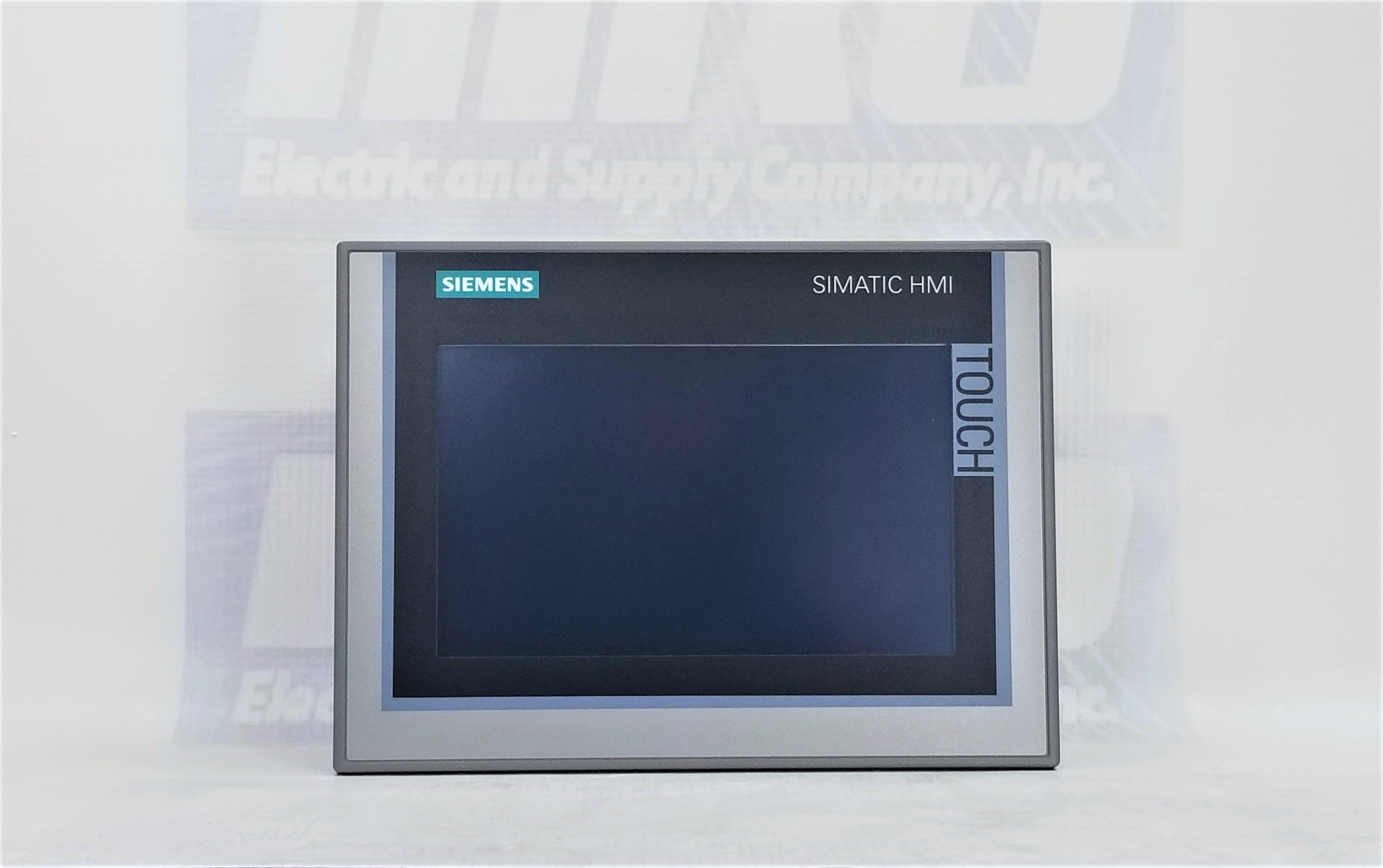
TP700 HMI Screen


Who is the TP700 Comfort Panel For?

The Siemens TP700 is the ideal solution for a wide range of mid-to-high-end applications across all industries. One of the first uses that come to mind is machine building. The TP700 brings a high level of control for machines perform tasks like assembling, injection molding, or complex packaging. Another industry that benefits from TP700 is the treatment and processing industry. Think water and waste treatment or chemical processing. The automotive industry is also another obvious choice as the TP700 gives the operator precision access to the assembly robots.

Conclusion

The Siemens TP700 Comfort Panel is more than just an interface; it’s a strategic investment in operational intelligence. By combining a brilliant display, powerful processing, rugged construction, and seamless integration within the TIA Portal, it empowers operators, simplifies processes, and provides the reliability required for 24/7 industrial operation. For engineers and system integrators looking to build advanced, efficient, and future-proof control systems, the TP700 Comfort Panel represents a benchmark in HMI technology.


Looking For a TP700

Are you in the market for a TP700, either new or refurbished? Reach our team of experts and let them help you get your operation running.

ICS Infrastructure in Automation Facilities

Industrial automation facilities rely heavily on Industrial Control Systems (ICS) to manage production lines, robotic systems, and machinery. Key components such as Programmable Logic Controllers (PLCs), Human-Machine Interfaces (HMIs), and motor drives are essential for operational efficiency. However, as these systems become more interconnected, they face growing cybersecurity risks that can lead to production downtime, safety hazards, and financial losses.

This article explores why securing ICS infrastructure is critical in automation facilities and how manufacturers implement protective protocols to safeguard their control systems.

Read more: ICS Infrastructure in Automation Facilities


Why ICS Security is Critical in Automation Facilities

The importance of ICS security in industrial automation goes beyond just simply protecting company assets. It also ensures employee safety and making sure production runs with minimal disruptions.

Protecting Intellectual Property & Supply Chains

Cyber espionage can steal trade secrets, affecting competitive advantage. A breach in one facility can cascade across the supply chain, delaying deliveries for automotive, pharmaceutical, and electronics industries. Having ICS security monitors and protects from any attacks or leaks of intellectual property.


Key Threats to ICS in Automation Facilities

Listed below are common threats that automation facilities face and their impacts. They highlight the crucial nature of ICS.

ThreatImpact on Automation Systems
RansomwareLocks HMIs, halts PLC operations, demands payment.
Malware (Stuxnet, Triton)Reprograms PLCs, damages motors, sabotages production.
Phishing AttacksGains access to engineering workstations controlling drives.
Insider ThreatsEmployees or contractors misuse access to modify PLC logic.
Unsecured Remote AccessHackers exploit VPNs or default passwords to take over HMIs.
Supply Chain AttacksCompromised firmware updates infect PLCs and drives.

Protocols for Securing ICS in Automation

Every company should systems and protocols in place to be able to respond quickly and effectively to attempts at breaches. Here are some suggested protocols that would help ensure optimal ICS security.

Network Segmentation

By separating OT networks from IT systems, you limit attack points from the outside. Be sure to use
industrial firewalls to filter traffic between PLCs, HMIs, and drives.

Securing Access Controls

By limiting security access to only the most vital roles, not only do you have control over access but also an easier way to determine where security vulnerabilities are. Security tools such as Role-based access control designates levels of access to an individual based on the role assigned to them. Likewise, multi-factor authentication limits remote accessibility for specific instruments like HMI’s to individuals with specific clearance. You can also assign temporary credentials for individuals who need specific access for a specific amount of time.

Security Patches and Firmware

Cybersecurity is a consistently evolving challenge that requires companies to have the most updated security features. This is often done through security firmware in the form of patches and updates. Having the most recent update to your firmware is crucial to making sure your system doesn’t fall victim to an unknown advanced virus or backdoor software.

VPN Encryption

Using a VPN encrypts the IP addresses of your PLC’s making it nearly impossible for a bad actor to gain remote access to them.

Conclusion

Securing ICS infrastructure in automation facilities is not optional—it’s a necessity to prevent operational disruptions, safety risks, and financial losses. By adopting protective protocols such as network segmentation, access controls, and real-time monitoring, manufacturers can defend their PLCs, HMIs, and drives from evolving cyber threats.

Automated Material Handling: Efficiency in a Modern Industry.

The modern landscape of industrialization is a chaotic mix of unnatural speed, precise accuracy, and unprecedented efficiency. This in large is thanks to the development of Automated Material Handling (AMH). AMH has emerged as a game-changing technology that optimizes the movement, storage, and control of materials within manufacturing, warehousing, and distribution environments. By leveraging robotics, artificial intelligence (AI), and advanced software systems. AMH reduces human intervention, minimizes errors, and enhances productivity.

What is AMH?

In short, AMH refers to the use of computerized and robotic systems to transport, store, and retrieve materials with minimal human involvement. Some examples of these systems include, conveyor systems for fast and efficient transport of materials across warehouses. Self-navigating robots/vehicles that can move materials around autonomous. These robots can also be paired with advanced storage systems to me retrieval a more streamlined process. Additionally robotic arms can quickly and safely pick up items that would normally be too heavy for one person to life. Robotic arms also serve a crucial role in automated assembly.

An example of a warehouse utilizing AMH.

The Importance of AMH

Automated Material Handling is a relatively new system that would make it easy to dismiss. However, in the short time it’s been around, it has made its role in automation absolutely crucial in keeping up with demand. On average, businesses that integrate AMH see about a 7.9% uptick in their annual growth. Of course speed is not the only factor that plays into this growth. Automating material handling reduces labor cost and increases efficiency with less margins of error.

While the initial cost of Automated Material Handling is undeniably high, the reduced labor, saving of space, and higher accuracy count makes it a great long term return on investment (ROI).

On a more technological level, AMH is designed to be scalable and upgradable integrating newer technologies such as AI. As a business grows, the operational space and systems are easily expandable to match that the pace and demands of that business. Likewise, AI-driven analytics ensure live tracking of inventory and orders.

Who Benefits from AMH

When we talk about industries that benefit most from automated material handling, manufacturing and retail tend to be at the forefront of what everyone thinks. AMH speeds up the manufacturing process in times that would take a team much longer to do. At the same time, the retail world utilizes AMH for rapid order fulfillment and warehouse distribution.

However, the pharmaceutical industry also utilizes AMH for handling hazardous materials and other substances. At the same time the food and beverage industry uses automated machine handling to keep their products at safe and preferable temperatures.

Conclusion

Automated Material Handling is no longer a luxury but a necessity for industries aiming to boost efficiency, cut costs, and stay competitive. By integrating AMH solutions, businesses can achieve faster operations, higher accuracy, and a safer work environment—paving the way for a smarter, more automated future.


Need Equipment?

Are you looking to get your automated? Perhaps you already are automated but need to get some parts replaced? Reach out to our team of experts to help connect you with the right equipment to get your operation up and running!


How to Test a Circuit Breaker

Circuit breakers are essential safety devices in any electrical system, protecting your home or workplace from overloading. Over time, they can wear out or malfunction, so it’s important to test them periodically to ensure they’re working correctly. In this guide, we’ll walk you through how to safely test a breaker.

Read more: How to Test a Circuit Breaker

The Importance of Testing a Circuit Breaker

There are different reasons to test circuit breakers. Where testing is most important, is in the area of safety. Regular testing of circuit breakers maintains safe electrical systems by preventing things like power surges which can damage equipment. Equipment isn’t the only safety concern that prompts regular breaker testing. Routine testing of circuit breakers can prevent fires from occurring.

Tools For Testing

When testing breakers, several tools are vital for conducting test. Among them, the tools most important are insulated gloves and a multi-meter. The insulated gloves are critical in safeguarding you from potential electrical hazards, and the multi-meter is important in circuit breaker diagnostics.

mutli-meters for testing circuit breakers

The Testing Process

Now that you know why and what equipment you’ll need to test, you’ll need to know how to test your circuit breaker. That step begins with turning off and unplugging devices along the circuit that is wired to the breaker. This prevents the security of any device or equipment you don’t want damaged. Once you’ve confirmed everything is unplugged, locate the breaker box. Usually the breaker box is located in places like a garage or basement.

The next step would be to visually scan for any signs of anything being off. That usually looks like burn marks, corrosion, or a tripped breaker. Any breaker that appear damaged should be replaced immediately. With your multimeter set to Voltage, test the breakers and circuits. A normal reading should show 120V for standard home circuits and 240V for larger circuits. A reading of 0 indicates a faulty breaker.

Perform a manual check by switching the breaker to the “ON’ position and then press the “TEST” button, the circuit should trip immediately. After tripping the breaker reset it back into the “ON” position, if it does not reset, then the breaker will need replacing.

If the breaker consistently fails voltage test, or trips without an obvious cause, call a professional electrician.


Conclusion

Testing a breaker is a simple but crucial maintenance task. By following these steps, you can ensure your electrical system remains safe and functional. If you’re unsure or encounter issues, always consult a licensed electrician for professional help.


Dirty Power

One of the biggest contributors to bad circuit breakers is what is commonly known as “dirty power”. More information about dirty power and how to prevent it can be found here.