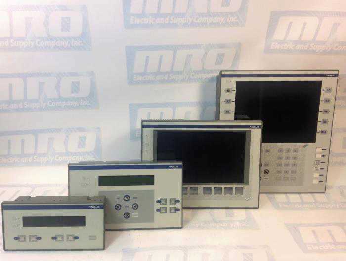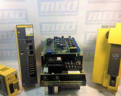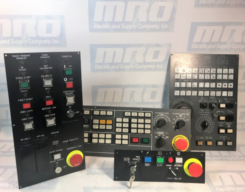
KUKA Controllers lineup

KUKA Error Codes

 KUKA robotics offers a broad range of robotics controllers and other robotics parts for a variety of industries including CNC machining, surface processing, loading usage, and much more. One common challenge with operating robotics controllers is understanding what the error codes mean, that they display when they encounter an issue. Listed below are common KUKA error messages that you may encounter while troubleshooting issues with KUKA controllers. These codes are applicable to all KUKA controllers, including the KRC1, KRC2, KRC3, and the KRC4.

Common KUKA KRC1, KRC2, KRC3, and KRC4 Error Codes

Error Code 14 – SOFTPLC: @P1@

Error Code 284 – Accu–voltage at <kps number> below <voltage level> during last buffering

  • Cause
    • The accu voltage was too low at the last switch off to buffer the
      shutdown.
    • The accu is not charged correctly anymore.
    • The accu is too old or broken.
  • Effect
    • Eventually loss of reference.
    • Cold boot.
    • Active commands inhibited
  • Remedy
    • Exchange accu.

Error Code 310 – Safety Circuit for drives not ready

  • Cause
    • Safety circuit is telling drives not to move.
    • Faulty X11
    • Faulty ESC board
    • Faulty KPS 600
  • Remedy
    • Check ESC monitor and other messages to narrow down the root cause with the safety circuit
    • Replace faulty components

Error Code 364 – Unknown operation mode

  • Possible Cause
    • Faulty KPS 600 Drive
  • Remedy
    • Replace KPS 600

Error Code 420 – Local protective stop (QE)

    • Possible Cause
      • Faulty KPS600 Drive
    • Remedy
      • Replace KPS600

Error Code 1033 – ERROR ON READING, DRIVER: ** **

Error Code 1034 – ERROR ON WRITING, DRIVER: ** **

Error Code 1133 – GEAR TORQUE EXCEEDED AXIS

  • Cause
    • The calculated gear torque is larger than the maximum permissible gear torque.
  • Monitor
    • Cyclic in interpolation cycle.
  • Effect
    • Motion and program are stopped.
  • Remedy
    • Reteach points.

Error Code 1239 – ACKN. SYNCHRONISATION ERROR DRIVE

Error Code 1376 – ACTIVE COMMANDS INHIBITED

  • Cause
    • A message which causes the active commands to be inhibited has been set.
  • Monitor
    • In command processing.
  • Effect
    • Command is not executed.
  • Remedy
    • Acknowledge active messages in the message window.

Error Code 2029 – SYNTAX ERROR IN KUKA MODULE

Error Code 2135 – NAME NOT DECLARED AS SUBROUTINE

Error Code 6502 – Error during reading INI file init/iosys.ini 1

  • Remedy
    • Check iosys.ini file
    • Ensure correct DeviceNET driver is installed
    • Check data cable between robot / cabinet

Error Code 10053

  • Remedy
    • Check fan to ensure it isn’t vibrating. This could be causing the Mfc card to move into the motherboard’s slot.

To find more info about KUKA error codes, view KUKA’s manual below.

View the KUKA Manual

MRO Electric carries replacement KUKA Robotics parts such as teach pendants, drives, motors, and more. To request a quote, please call 800-691-8511 or email sales@mroelectric.com.

Troubleshooting error codes on your KUKA controller?

We can help you resolve issues with your KUKA controllers. Whether you’re looking to repair your old controller or purchase a new one, we’re dedicated to keeping your automation systems running at their best!

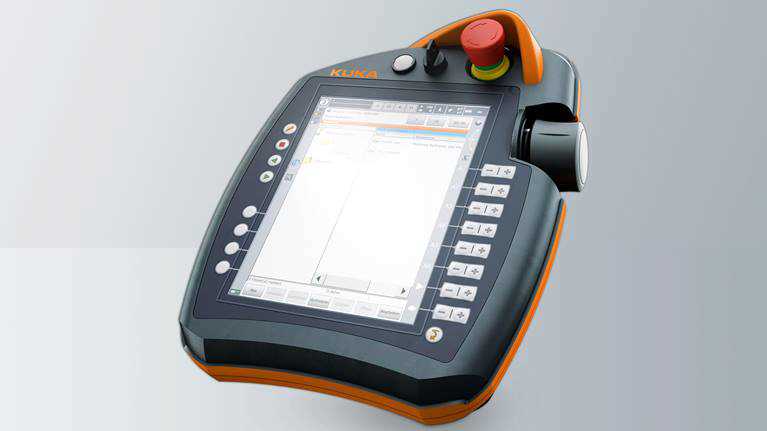
KUKA teach pendant

KUKA Teach Pendants

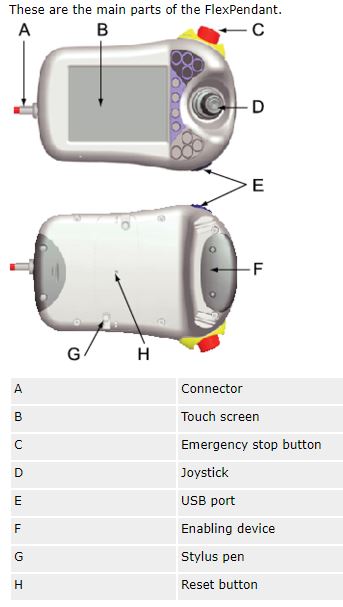
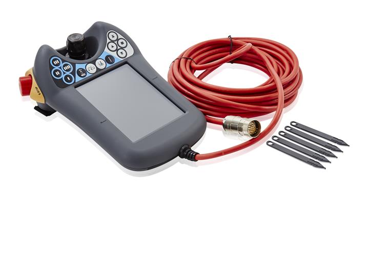
MRO Electric and Supply distributes a variety of KUKA Teach Pendants for KRC1, KRC2, and KRC3 controls. We also can supply the new KRC4 smartPAD. The smartPAD pendant  is the latest type of KUKA teach pendant, designed to allow users to perform even the most complex operating tasks with ease – even those with little experience.  It features an 8.4″ display size with a industrial touch screen.

KUKA smartPAD Teach Pendant

The ergonomic design of the KUKA smartPAD creates a pendant with reduced weight and an anatomically comfortable operation. It can be used to operate all KUKA robots that have a KR C4 controller. Its 6D mouse allows for movement and reorientation of the robot on all axes.

All smartPADs are programmed using the KRL – KUKA programming language. This easy to learn robotics language is very intuitive, and can be used to create customized robotic motions with ease. You can also synchronize your programming with up to 6 KUKA robots. The other major benefit of the smartPAD teach pendant is that  it can be hot swapped at any time from a KR C4 controller – just simply plug it in and use.

Legacy KUKA Teach Pendants

MRO Electric also distributes a number of legacy KUKA teach pendants. We recognize that there are still a variety of older KUKA controllers still in use today. Rather than having to upgrade your control system when one of your pendants fail, we can ship you a replacement pendant to minimize any downtime.

If for some reason our stock is depleted, we can usually repair your KUKA pendant in as little as 3-5 days. Visit our main KUKA product page to see all the KUKA teach pendants that we can supply or repair.

For more information or to request a quote on a replacement pendant or panel, please call 800-691-8511 or email sales@mroelectric.com.

PLC Security

Programmable logic controllers, also known as PLCs, initially came about in the late 1960s. PLCs were designed to replace relay-based machine control systems in the major U.S. vehicle manufacturing space. The relay-based control systems were considered hard to use and were disliked amongst those in the automation and manufacturing in.

In 1968, Dick Morley of Bedford Associates in Massachusetts designed the Modular Digital Controller, later dubbed the Modicon. After the Modicon 084’s initiation into the world, there was no looking back to those relay-based control systems. Be sure to check out our article covering Modicon PLC history to learn more.

PLCs are user-friendly microprocessor-based specialty computers that carry out control functions, many of which are of high levels of complexity. They are engineered to endure harsh and strenuous situations such as in heated, cooled and even moist environments. Used for automation usually in the industrial electromechanical space, PLCs are computers that deal with the controlling of machinery, often on  the following:

  • factory assembly lines
  • power stations
  • distribution systems
  • power generation systems
  • gas turbines

PLCs are programmed using a computer language. Written on a computer, the program is then downloaded to the PLC via a cable. These programs are stored in the PLCs memory. The hard-wired logic is exchanged for the program fed by its user during the transition between relay controls to PLC. The manufacturing and process control industries have gotten to take advantage of PLC applications-oriented software since Modicon PLCs inception.

plc security
PLC Functions and Directions

PLCs use programmable memory in order to store particular functions and directions. Some functions and directions would include:

  • on control
  • off control
  • timing
  • sequencing
  • counting
  • arithmetic
  • data manipulation
PLC Types

Understanding the different types of PLCs will be very helpful when looking into PLC security.

The numerous types of PLCs can be organized into three principal categories:

  • Advanced PLC: Advanced PLCs offer the greatest processing power out of all of the PLC types. They feature a larger memory capacity, higher input/output (I/O) expandability, and greater networking options.
  • Compact Controller: Logic Controllers are increased intermediate level offerings with an increased set of instructions and a greater input/output (I/O) than a run-of-the-mill logic controller
  • Logic Controler: A logic controller is often referred to as a ‘smart relay’. They are generally straightforward to use and considered a good place to begin when becoming acquainted with PLCs. They are cost-effective for low input/output (I/O), slower speed applications.
PLC Security

As security concerns remain in many professional spaces including the factory automation space, becoming up-to-speed with the different types of PLC Security is imperative. By creating and implementing an effective strategy to remain secure, you will likely avoid issues, downtime, and setbacks. Understanding the different types of PLCs will be very helpful when looking into PLC security.

PLC Cybersecurity: How the control network is linked to the internet, as well as other networks. A handful of PLC issues could likely involve the following:

  • Incident response planning and plans;
  • Issues drafting and reviewing policies
  • Issues drafting and reviewing procedures
  • Retention of cybersecurity experts and vendors;
  • A need for preparation of a breach:
    • exercises
    • training
    • breach simulations
  • A need for cybersecurity insurance review and counseling
  • A demand for record management and information infrastructure;
  • Privacy risk management
  • Assessment of cybersecurity risk in mergers and acquisitions;
  • Payment Credit Industry (PCI) Compliance protocols
  • Vendor contract management protocols
  • Supply chain risk management

PLC Physical Security: Although PLC physical security differs from PLC cybersecurity, it is still important and should be prioritized when an individual or a company is undergoing breach simulations, training, and exercises. PLC physical security deals with:

  • correcting default passwords
  • ensuring only certified individuals are in the control system’s environment
  • limiting access to thumb drives and securing access

MRO Electric and Supply maintains a comprehensive stock of Modicon PLC parts, including the Modicon Quantum series. Also, feel free to check out our repair and core exchange programs to learn how to save.

Understanding Issues with Security
In order to create and implement training and procedures for staff, you must understand how issues with security occur.  Not all cybersecurity attacks occur from external hackers or scammers. In fact, experts believe that only an estimated 20% of all cybersecurity attacks are intentional and intended to be malicious. Whether you think it’s possible or not, an offended employee could indeed be your hacker. Almost always caused by software issues, device issues, and malware infections, cybersecurity seems straight-forward initially, until you dig into those fine, often overlooked details.

As many in the automation space may know, PLC cybersecurity wasn’t a thing a decade ago. These days, PLCs are connected to business systems through any run-of-the-mill network and aren’t separated from other networks that other automation equipment may also be on.  As time goes on, it’s becoming more and more common to see TCP/IP networking from a business system standpoint. By connecting via TCP/IP, data exchange, as well as more rational and scalable business decisions, is enabled.

PLC Security Factors:
  • Although it may not actually connect to the internet, a control system is unsafe. Contrary to popular belief, a modem connection could also experience intrusion and a hack.
  • Wireless networks, laptop computers, and trusted vendor connections could be other sources of connections in which people may be likely to overlook.
  • Keep in mind that the majority of IT departments are unaware of factory automation equipment, including CNCs, CPUs, PCBs, robotics parts and, last but not least, PLCs.
  • Piggybacking off of the last point, IT departments’ lack of experience with the aforementioned equipment, along with their lack of experience with industrial standards and scalable processes indicate that they should not be in-charge and responsible for a company’s PLC security. Nobody wants an annoyed employee to make inappropriate changes to a PLC’s communication highway.
  • Hackers do not necessarily need to understand PLC or SCADA to block PC-to-PLC communication. They absolutely do not need to understand a PLC or SCADA system to cause operational or programming issues.
  •  Often times, control systems, including ones that many PLCs integrate with, use Microsoft Windows, which is very popular amongst hackers.
  • Some PLCs crash simply by pinging an IP address, like what happened at the Brown’s Ferry Nuclear Plant, which is located in upstate Alabama. Since the incident in 2006, the plant has undergone numerous security, operational, and management improvements.

In conclusion, when a security breach occurs, regardless of the specifics, understanding that time is of the essence will help smooth over most incidents. Trusting who has access to a control systems environment and thumb drive is crucial. If someone has access to the control system environment and thumb drive, ensure they’re well-qualified and up-to-speed with their team and/or company.

FANUC 18i M-Codes

Fanuc Motors

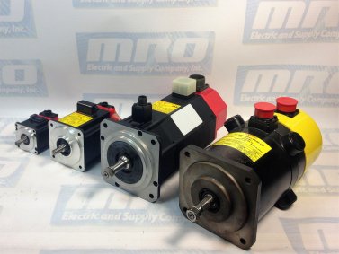
In the world of automation, whether we’re talking about factory or shop automation, understanding how to operate and maintain FANUC CNC parts is imperative. Several businesses and companies suffer from dreaded downtime because a team isn’t well-rounded; many team members may know how to manage machine operators, etc., but are unaware of how to operate a CNC themselves. For a manager, knowing and understanding exactly what to look for to avoid an operating issue starts with understanding the basics of CNC machining and programming.

CNCs originally started coming about in the late 1940s, not long after World War II as NCs (Numerical Controls). They were engineered to be a reliable, cost-effective way to manufacture and design an increased amount of parts for the aircraft industry. Based on already-existing modified tools equipped with motors that manipulated the controls, CNCs were quickly and abruptly built up with computers, both digital and analog. As time has gone on, CNCs have continued to evolve as technology evolves.

Early Numerical Controls initially lacked computers. They also lacked calculating ability, which is absolutely unheard of in today’s world. After the 1960s, numerical controls eventually gained calculating and computer functions. Onboard processing became feasible and, as a result, CNC machines came about. Via the initiation of CNCs, a handful of features were then attainable, fortunately, including canned cycles, tool length compensation, sub programming, radial compensation and tool diameter.

Preparatory Codes

NC and CNC G Codes are referred to as preparatory codes. By preparing the machine to perform a specific function like, for example, rapid travel G0 / G00, the preparatory process is important to understand, as all of the stages of production are.

Miscellaneous Codes

NC / CNC M codes are known as miscellaneous codes.  CNC M codes basically perform on and off functions such as:

  • stopping processing of CNC code M0 / M00
  • turning the spindle on M3 / M0 or M3 / M03
  • stopping the spindle M5 / M05
  • turning coolant on M8 / M08

MRO Electric and Supply has new and refurbished FANUC CNC parts available. We also offer repair pricing. For more information, please call 800-691-8511 or email sales@mroelectric.com.

G Code and M Code

The ANSI standard for G code and M code programming is ANSI/EIA 274D-1988. The ISO standard for G code and M code programming is ISO 6983. There is a new and different standard ISO 14649 also known as the STEP-NC standard that addresses NC and CNC programming using the enhanced features of CAD and/or CAM software.

Machine tool builders are not required to adhere to standards and every so often create variations to standard G codes and M codes. Occasionally design different, unique alternatives to orthodox G codes and M codes. Typically, the majority of CNC G codes are considered modal, which means they stay active until they’re changed. Along with understanding CNC codes, feel free to view another one of our articles focused on choosing a CNC to become as well-versed with CNCs as possible.

Auxiliary Function (M Function)

When a numeral is specified following address M, code signal and a strobe signal are sent to the machine. The machine uses these signals to turn on or off its functions. Usually, only one M code can be specified in one block.

In some cases, however, up to three M codes can be specified for some types of machine tools. Which M code corresponds to which machine function is determined by the machine tool builder.

The machine processes all operations specified by M codes except those specified by M98, M99,M198 or called subprogram(Parameter No.6071 to 6079), or called custom macro (Parameter No.6080 to 6089). Refer to the machine tool builder’s instruction manual for details.

The following M codes have special meanings:
  • M02, M03 (End of Program)
    • This indicates the end of the main program Automatic operation is stopped and the CNC unit is reset.
    • This differs with the machine tool builder. After a block specifying the end of the program is executed, control returns to the start of the program. Bit 5 of parameter 3404 (M02) or bit 4 of parameter 3404 (M30) can be used to disable M02, M30 from returning control to the start of the program.
  • M00 (Program Stop)
    • Automatic operation is stopped after a block containing M00 is executed. When the program is stopped, all existing modal information remains unchanged. The automatic operation can be restarted by actuating the cycle operation. This differs with the machine tool builder.
  • M01 (Optional Stop)
    • Similarly to M00, automatic operation is stopped after a block containing M01 is executed. This code is only effective when the Optional Stop switch on the machine operator’s panel has been pressed.
  • M98 (Calling of Sub-Program)
    • This code is used to call a subprogram. The code and strobe signals are not sent.
  • M99 (End of Subprogram)
    • This code indicates the end of a subprogram. M99 execution returns control to the main program. The code and strobe signals are not sent.
  • M198 (Calling a Subprogram)
    • This code is used to call a subprogram of a file in the external input/output function. See the description of the subprogram call function (III–4.7) for details.
Multiple M Commands in a Single Block

In general, only one M code can be specified in a block. However, up to three M codes can be specified at once in a block by setting bit 7 (M3B) of parameter No. 3404 to 1. Up to three M codes specified in a block are simultaneously output to the machine. This means that compared with the conventional method of a single M command in a single block, a shorter cycle time can be realized in machining.

CNC allows up to three M codes to be specified in one block. However, some M codes cannot be specified at the same time due to mechanical operation restrictions. For detailed information about the mechanical operation restrictions on simultaneous specification of multiple M codes in one block, refer to the manual of each machine tool builder. M00, M01, M02, M30, M98, M99, or M198 must not be specified together with another M code. Some M codes other than M00, M01, M02, M30, M98, M99, and M198 cannot be specified together with other M codes; each of those M codes must be specified in a single block.

Such M codes include these which direct the CNC to perform internal operations in addition to sending the M codes themselves to the machine. To be specified, such M codes are M codes for calling program numbers 9001 to 9009 and M codes for disabling advance reading (buffering) of subsequent blocks. Meanwhile, multiple of M codes that direct the CNC only to send the M codes themselves (without performing internal operations ) can be specified in a single block.

M Code Group Check Function

The M code group check function checks if a combination of multiple M codes (up to three M codes) contained in a block is correct.

This function has two purposes. One is to detect if any of the multiple M codes specified in a block include an M code that must be specified alone. The other purpose is to detect if any of the multiple M codes specified in a block include M codes that belong to the same group. In either of these cases, P/S alarm No. 5016 is issued. For details on group data setting, refer to the manual available from the machine tool builder.

  • M Code Setting
    • Up to 500 M codes can be specified. In general, M0 to M99 are always specified. M codes from M100 and up are optional.
  • Group Numbers
    • Group numbers can be set from 0 to 127. Note, however, that 0 and 1 have special meanings. Group number 0 represents M codes that need not be checked. Group number 1 represents M codes that must be specified alone.
Choosing a FANUC CNC

fanuc cnc

Choosing a CNC

Buying and building a new CNC (view FANUC CNC parts) can be challenging and often nerve-racking. Regardless of which space you’re in, downtime needs to be avoided as much as humanly (or robotically) possible.  Check out our points to avoid common CNC issues.

One of the most common reasons for CNC downtime would be low build quality. Balls screws,  linear guides, and linear boxes need to be built with high quality to avoid downtime. Often, unfortunately, CNC machines are built using several high-quality parts, and a handful of cheaper, lower-quality parts. Although a machine may consist of mainly high-quality, top-of-the-line parts, issues are still likely to occur due to the low-quality parts. A CNC machine, like most pieces of machinery, is ‘only as strong as its weakest link’.

By taking a look at the tool changer’s location, you can usually determine if its location will be an issue or not. Faulty tool changer designs are common in the CNC world. If it’s hard to get to the tool changer to, for example, change and replace the cam followers, then another design alternative may be best. Don’t be afraid to research other up-to-par designs and designs that have worked well for others in the past.

Avoid poor-quality spindles at all costs, as they’re everywhere and often result in issues. Take a good look at the spindles’ bearings. If they’re plentiful and look larger-than-average, you’re good to go. If they’re lacking in size, research instances where spindles’ bushings have been an issue to create your standard. Along with that, take a look at the horsepower of them; if their horsepower is below average, avoid at all costs. Stalling may occur with low horsepower spindles, which often results in many others with other parts on top of the spindle. Also, be sure to check out our article focused on maintaining automation machine tools. Maintenance is unavoidable and compiling maintenance with unnecessary rebuilds is unpractical and will likely result in downtime and lost profit.

Tolerance of CNCs should be tight. The tighter the tolerance, the longer the life expectancy generally is. Tighter tolerance will also result in an overall smoother operation. MRO Electric and Supply has new and refurbished FANUC CNC parts available. We also offer repair pricing. For more information, please call 800-691-8511 or email sales@mroelectric.com.

Factory Automation and Machine-to-Machine (M2M) Advances

fanuc robotics

 Factory Automation and Machine-to-Machine (M2M) Advances

As technology evolves, automation has become more and more prevalent in the factory automation space. Machine-to-machine enables private and exclusive communication and control over sensors, cameras, industrial equipment, robotics (check out our FANUC Robotics parts) and essentially anything else. Manufactory facilities and several other remote systems are managed much more easily with machine-to-machine advances in communication.

Initially, with industrial and enterprise applications as a focal point, machine-to-machine communication was easily defined and used for a limited amount of tasks. Nowadays, there are many fewer limitations associated with the machine-to-machine communication.

Pressured to lower costs and improve speed and overall efficiency, factory automation companies are often in an uncomfortable spot. While using high-end, sophisticated automation applications and tools, more real-time data must be obtained to streamline more of the day-to-day operations and tasks. Implementing machine-to-machine solutions can help with operational efficiency gains, time and cost savings, and performance optimization.

From a cellular standpoint, machine-to-machine solutions enable integration of environmental controls into a single system, and to unify with security and video surveillance systems. All and all, companies are able to secure several properties from anywhere they wish to, even as they fine-tune power efficiency and decrease operating expenses.

Due to the immense increase of machine-operated plants in companies who rely on keeping critical assets and functions performing optimally, several companies are exploring options associated with a machine-to-machine communication. Of the many benefits, the fact that it’s able to deliver remote access to gather real-time process data to cut operation costs is often one of the most well-recognized. The ability to identify and rectify production line faults, or design and implement preventative maintenance strategies, for example, is what machine-to-machine communication is designed for.

Involving data exchange over the telephone line or via the internal with machines, plants, computers for issue detection, diagnostics, and repair, teleservice is an imperative aspect of machine-to-machine communication. Offering an optimal answer to diagnose distant systems, teleservice is becoming more and more popular and is not going anywhere.

Telecontrol, another aspect of machine-to-machine communication, deals with connections of distant process stations to one or more central control systems. Many networks, both public and private,  can be used for communication used to control. For these diverse applications and businesses, cellular M2M connectivity can address many business and technical challenges and enable important benefits.

MRO Electric and Supply has new and refurbished FANUC parts available. We also offer repair pricing. For more information, please call 800-691-8511 or email sales@mroelectric.com.

Additionally, M2M systems can be designed to withstand harsh environmental conditions and easily manage and control connected devices across the country or around the world. M2M systems provide flexibility to move equipment as needed, or bring up and tear down systems quickly for temporary or seasonal deployments. By using modern M2M management and application platforms, and taking care to choose platforms designed to meet real-world requirements, organizations can take full advantage of the M2M revolution.

In case you were wondering, machine-to-machine systems are indeed designed to withstand environmental conditions and easily control connected devices in any location. They are flexible and can move equipment with ease. In order to use machine-to-machine communication optimally, look into management and application platforms. Click here to view our article on IT and Robotics.

Boosting Factory Automation Productivity

Boosting Factory Automation Productivity

In the factory automation space, productivity is much more than an imperative management concept; it is a scalable tool that drives employees and processes to be functioning at their best. In order to keep employees on track and enable goals to be met in the workplace, fine-tuning processes and running a ‘tight ship’ as far as time management is concerned is considered best practice.

As far as work is concerned, understanding where to start is the first, and often, most difficult step. Understand what may set your company back, whether it be a worn down motor (such as a FANUC CNC Motor) not performing up-to-par, or a poorly-maintained Servo Amp (such as a FANUC CNC Servo Amp).  Missing expectations due to a faulty machine is avoidable, as seen in this article focusing on Maintaining Automation Machine Tools.

To ensure your teams’ insights aren’t hindered, consider documenting priority-oriented processes such as customer service, client retention, and cutting operation costs, that way, more focus can be put toward improving workflow, coaching employees and pinpointing other areas that could be improved on. Take industry benchmarks into consideration; they can be used as a point of reference to determine if an area can be improved in, or if it’s already up-to-par. Along with documenting the aforementioned processes, keeping track of progress and growth can also aid in fine-tuning.

In order to remain on the same page with employees, ask for their buy-in and try to understand where they’re coming from. They may help shed light on problematic areas such as why certain departments aren’t working as closely together as they could be, or if downtime could be minimized by having two departments working together more effectively. By making employees feel valued and trusted, a company is less likely to run into honesty issues, communication issues and/or issues with collaboration. The foundation for productive operations starts with an honest, well-communicating team. Teams need to have an in-depth understanding of where they’re expected to add value and, of course, what the company is working toward as a whole. Eliminating clutter in order to have a well-focused and productive team is an achievement that most of those in the factory machine automation space don’t lose sight of. MRO Electric and Supply has new and refurbished FANUC CNC parts available. We also offer repair pricing. For more information, please call 800-691-8511 or email sales@mroelectric.com.

These days, there are shortcuts and tools for essentially any and every niche. Many of those in the machine and factory automation space are focusing on robotics (see FANUC Robotics parts) to explore ways to automate processes in hope of enhancing productivity. Be sure to stay ‘in the loop’ when it comes to tools that could enhance one’s productivity through collaboration, etc.