As a generic name for a plain-text language that CNC machines are able to understand, G-Codes are important to understand in the manufacturing, automation and engineering spaces. You can enter a G-Code manually if you wish, but you do not have to because of the CAD/CAM software’ abilities along with the machine controller. G-Codes are not necessarily readable by humans, but it’s possible to look through the file and determine what is generally occurring.
What Is G Code?
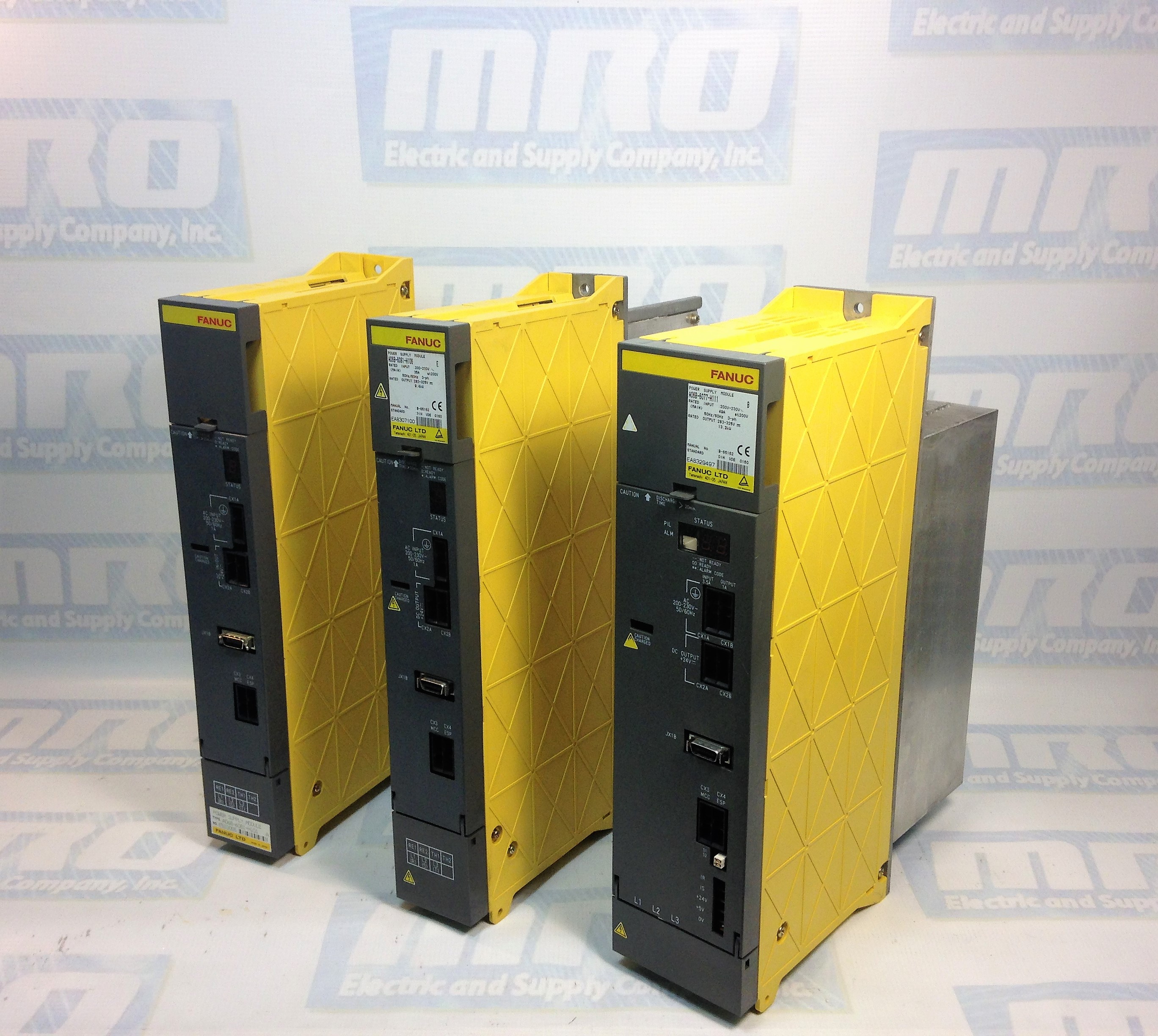
In the factory automation space, nobody likes downtime and receiving error codes. While using CNCs (view FANUC CNC parts here), many professionals are faced with G Codes. By definition, a G Code is a computer code language that is used to guide CNC machine devices to perform specific motions.
What Do CNC G Codes Do?
G Codes are important because they allow easy, repeatable control of the motion of a CNC machine. A few examples of specific motions that CNC G Codes can control, would be:
- canned cycles
- work coordinates
- several repetitive cycles.
Canned Cycles
Also referred to as a fixed cycle, canned cycles are ways to effectively and efficiently perform repetitive CNC machining operations. They automate specific machining functions. A few examples would be pocketing, threading, and drilling. A canned cycle is almost always stored as a pre-program in a machine’s controller. To learn more about canned cycles, check out this article courtesy of zero-divide.net.
Work Coordinates
The G Code coordinate pipeline goes something like this:
- Unit conversion to metric
- Convert from relative to absolute and polar to Cartesian: g90g91XYZ()
- G52, G54, and G92 offsets
- G51 scaling
- G68 coordinate rotation
G-Code is the most popular programming language used for programming CNC machinery. Some G words alter the state of the machine so that it changes from cutting straight lines to cutting arcs. Other G words cause the interpretation of numbers as millimeters rather than inches. Some G words set or remove tool length or diameter offsets. Be sure to check out our article covering FANUC CNC Codes, including FANUC M Codes, here.
MRO Electric and Supply has new and refurbished FANUC CNC parts available. We also offer repair pricing. For more information, please call 800-691-8511 or email sales@mroelectric.com.
What Are the Different Types of G Code Commands?
Listed below are some easily-understood G-code commands in which are used for setting the speed, feed, and tool parameters.
F= Feed
The F value in G-code is used to set the feed rate, which determines the speed at which the machine’s extruder or tool head moves. F values are typically measured in millimeters per minute (mm/min), so dividing the F value by 60 converts it to millimeters per second (mm/s). For instance, an F value of F1500 means the feed rate is 25 mm/s. The machine operates at this specified feed rate when a G1 command is used, which is essential for precise control of the movement speed.
It is crucial to set the feed rate (F) before the first G1 command to avoid errors. Here’s an example of setting the feed rate:
In this example, the machine will move to the coordinates X100 Y100 at a speed of 1500 mm/min (25 mm/s).
S= Spindle Speed
The S command’s purpose is to set the spindle speed. The Spindle speed is almost always set in RPMs (revolutions per minute). Here is an example:
T= Tool
The T command’s purpose is paired with M6 in order to display the tool number to be used for cutting the current file. Here is an example:
Common G Code Command List
Below is a comprehensive list of common CNC G Codes, designed to guide you through the essential programming for CNC machines.
- G00 Rapid traverse
- G01 Linear interpolation with feed rate
- G02 Circular interpolation (clockwise)
- G03 Circular interpolation (counterclockwise)
- G2/G3 Helical interpolation
- G04 Dwell time in milliseconds
- G05 Spline definition
- G06 Spline interpolation
- G07 Tangential circular interpolation, Helix interpolation, Polygon interpolation, Feedrate interpolation
- G08 Ramping function at block transition / Look ahead “off”
- G09 No ramping function at block transition / Look ahead “on”
- G10 Stop dynamic block preprocessing
- G11 Stop interpolation during block preprocessing
- G12 Circular interpolation (CW) with radius
- G13 Circular interpolation (CCW) with radius
- G14 Polar coordinate programming, absolute
- G15 Polar coordinate programming, relative
- G16 Definition of the pole point of the polar coordinate system
- G17 Selection of the X, Y plane
- G18 Selection of the Z, X plane
- G19 Selection of the Y, Z plane
- G20 Selection of a freely definable plane
- G21 Parallel axes “on”
- G22 Parallel axes “off”
- G24 Safe zone programming; lower limit values
- G25 Safe zone programming; upper limit values
- G26 Safe zone programming “off”
- G27 Safe zone programming “on”
- G33 Thread cutting with constant pitch
- G34 Thread cutting with dynamic pitch
- G35 Oscillation configuration
- G38 Mirror imaging “on”
- G39 Mirror imaging “off”
- G40 Path compensations “off”
- G41 Path compensation left of the workpiece contour
- G42 Path compensation right of the workpiece contour
- G43 Path compensation left of the workpiece contour with altered approach
- G44 Path compensation right of the workpiece contour with altered approach
- G50 Scaling
- G51 Part rotation; programming in degrees
- G52 Part rotation; programming in radians
- G53 Zero offset off
- G54 Zero offset #1
- G55 Zero offset #2
- G56 Zero offset #3
- G57 Zero offset #4
- G58 Zero offset #5
- G59 Zero offset #6
- G63 Feed/spindle override not active
- G66 Feed/spindle override active
- G70 Inch format active
- G71 Metric format active
- G72 Interpolation with precision stop “off”
- G73 Interpolation with precision stop “on”
- G74 Move to home position
- G75 Curvature function activation
- G76 Curvature acceleration limit
- G78 Normalcy function “on” (rotational axis orientation)
- G79 Normalcy function “off”
Milling Applications
- G80 Canned cycle “off”
- G81 Drilling to final depth canned cycle
- G82 Spot facing with dwell time canned cycle
- G83 Deep hole drilling canned cycle
- G84 Tapping or Thread cutting with balanced chuck canned cycle
- G85 Reaming canned cycle
- G86 Boring canned cycle
- G87 Reaming with measuring stop canned cycle
- G88 Boring with spindle stop canned cycle
- G89 Boring with intermediate stop canned cycle
Cylindrical Grinding Applications
- G81 Reciprocation without plunge
- G82 Incremental face grinding
- G83 Incremental plunge grinding
- G84 Multi-pass face grinding
- G85 Multi-pass diameter grinding
- G86 Shoulder grinding
- G87 Shoulder grinding with face plunge
- G88 Shoulder grinding with diameter plunge
- G90 Absolute programming
- G91 Incremental programming
- G92 Position preset
- G93 Constant tool circumference velocity “on” (grinding wheel)
- G94 Feed in mm / min (or inch / min)
- G95 Feed per revolution (mm / rev or inch / rev)
- G96 Constant cutting speed “on”
- G97 Constant cutting speed “off”
- G98 Positioning axis signal to PLC
- G99 Axis offset
- G100 Polar transformation “off”
- G101 Polar transformation “on”
- G102 Cylinder barrel transformation “on”; cartesian coordinate system
- G103 Cylinder barrel transformation “on,” with real-time-radius compensation (RRC)
- G104 Cylinder barrel transformation with centerline migration (CLM) and RRC
- G105 Polar transformation “on” with polar axis selections
- G106 Cylinder barrel transformation “on” polar-/cylinder-coordinates
- G107 Cylinder barrel transformation “on” polar-/cylinder-coordinates with RRC
- G108 Cylinder barrel transformation polar-/cylinder-coordinates with CLM and RRC
- G109 Axis transformation programming of the tool depth
- G110 Power control axis selection/channel 1
- G111 Power control pre-selection V1, F1, T1/channel 1 (Voltage, Frequency, Time)
- G112 Power control pre-selection V2, F2, T2/channel 1
- G113 Power control pre-selection V3, F3, T3/channel 1
- G114 Power control pre-selection T4/channel 1
- G115 Power control pre-selection T5/channel 1
- G116 Power control pre-selection T6/pulsing output
- G117 Power control pre-selection T7/pulsing output
- G120 Axis transformation; orientation changing of the linear interpolation rotary axis
- G121 Axis transformation; orientation change in a plane
- G125 Electronic gearbox; plain teeth
- G126 Electronic gearbox; helical gearing, axial
- G127 Electronic gearbox; helical gearing, tangential
- G128 Electronic gearbox; helical gearing, diagonal
- G130 Axis transformation; programming of the type of the orientation change
- G131 Axis transformation; programming of the type of the orientation change
- G132 Axis transformation; programming of the type of the orientation change
- G133 Zero lag thread cutting “on”
- G134 Zero lag thread cutting “off”
- G140 Axis transformation; orientation designation workpiece fixed coordinates
- G141 Axis transformation; orientation designation active coordinates
- G160 ART activation
- G161 ART learning function for velocity factors “on”
- G162 ART learning function deactivation
- G163 ART learning function for acceleration factors
- G164 ART learning function for acceleration changing
- G165 Command filter “on”
- G166 Command filter “off”
- G170 Digital measuring signals; block transfer with hard stop
- G171 Digital measuring signals; block transfer without hard stop
- G172 Digital measuring signals; block transfer with smooth stop
- G175 SERCOS-identification number “write”
- G176 SERCOS-identification number “read”
- G180 Axis transformation “off”
- G181 Axis transformation “on” with not rotated coordinate system
- G182 Axis transformation “on” with rotated/displaced coordinate system
- G183 Axis transformation; definition of the coordinate system
- G184 Axis transformation; programming tool dimensions
- G186 Look ahead; corner acceleration; circle tolerance
- G188 Activation of the positioning axes
- G190 Diameter programming deactivation
- G191 Diameter programming “on” and display of the contact point
- G192 Diameter programming; only display contact point diameter
- G193 Diameter programming; only display contact point actual axes center point
- G200 Corner smoothing “off”
- G201 Corner smoothing “on” with defined radius
- G202 Corner smoothing “on” with defined corner tolerance
- G203 Corner smoothing with defined radius up to maximum tolerance
- G210 Power control axis selection/Channel 2
- G211 Power control pre-selection V1, F1, T1/Channel 2
- G212 Power control pre-selection V2, F2, T2/Channel 2
- G213 Power control pre-selection V3, F3, T3/Channel 2
- G214 Power control pre-selection T4/Channel 2
- G215 Power control pre-selection T5/Channel 2
- G216 Power control pre-selection T6/pulsing output/Channel 2
- G217 Power control pre-selection T7/pulsing output/Channel 2
- G220 Angled wheel transformation “off”
- G221 Angled wheel transformation “on”
- G222 Angled wheel transformation “on” but angled wheel moves before others
- G223 Angled wheel transformation “on” but angled wheel moves after others
- G265 Distance regulation – axis selection
- G270 Turning finishing cycle
- G271 Stock removal in turning
- G272 Stock removal in facing
- G274 Peck finishing cycle
- G275 Outer diameter / internal diameter turning cycle
- G276 Multiple pass threading cycle
- G310 Power control axes selection /channel 3
- G311 Power control pre-selection V1, F1, T1/channel 3
- G312 Power control pre-selection V2, F2, T2/channel 3
- G313 Power control pre-selection V3, F3, T3/channel 3
- G314 Power control pre-selection T4/channel 3
- G315 Power control pre-selection T5/channel 3
- G316 Power control pre-selection T6/pulsing output/Channel 3
- G317 Power control pre-selection T7/pulsing output/Channel 3
In conclusion, becoming well-versed on CNC G-Codes, along with other codes associated with CNCs is imperative in this day and age. By having up-to-speed knowledge of CNC codes, you could most definitely set yourself apart from the average Joe.