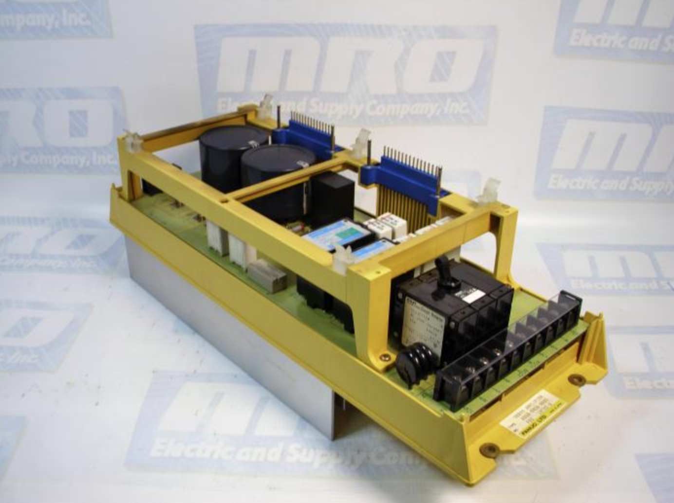
Powering Up a Siemens PCU 50 (Siemens Simodrive)

Siemens Simodrive

Powering Up a Siemens PCU 50 (Siemens Simodrive)

Recently we had a customer who we helped to walk through with booting up a 6FC5210-0DF22-0AA0 Siemens Simodrive PCU 50 unit that they were replacing. Their original unit was starting up and then freezing after several minutes so they decided to go ahead and replace the unit, as their original was diagnosed as having a blown main board which was not repairable. There were some issue with getting the replacement up and running, so we wanted to give a simple explanation for powering up a 6FC5210-0DF22-0AA0 unit (view Siemens CNC Simodrive Series parts here), along with an accompanying video showing the final result.

To start, the PCU 50 need to be hooked up to 24VDC power using the accompanying green plug. On the PCU 50 itself there is a wiring diagram showing all of the connections for the ground and the +/-. Next, the display monitor is hooked up to the VGA port, and then the keyboard/mouse are hooked into either the USB connections or the designated connections on the side of the 6FC5210-0DF22-0AA0 unit. Before powering on the unit, you need to make sure to turn the black knob on the CPU card from the “non-operating” position to the “operating” position. If it is not changed the unit will still power on, but you will be unable to access the CPU. Once everything is set you can turn on the DC power and the 6FC5210-0DF22-0AA0 will power up successfully, bringing you to the login screen.

Here is a link to a video showing the connections and the booting process.

MRO Electric stocks new and refurbished Siemens CNC Simodrive parts. We also provide pre-priced Control Techniques repairs. For more information or to request a quote, please call 800-691-8511 or email sales@mroelectric.com.

Replacing a 140CPU43412 With a 140CPU43412A CPU

140CPU43412A CPU

Replacing a 140CPU43412 With a 140CPU43412A CPU

One of the more common Modicon Quantum CPU modules is the 140CPU43412A CPU module. This unit replaced the 140CPU43412 unit which has since become obsolete. Currently, many systems are being updated so we consistently get questions about 140CPU43412A CPU replacement and what the differences between the two units are, and if they are plug-and-play replacements. To help with this transition, we put together a few notes to help anyone who has questions.

The redesigned unit designated with the “A” at the end is functionally identical to the original non-“A” unit, with a few slight considerations. If you are using this CPU in a hot standby system, you must use matching units, so either two 140CPU43412 units or two 140CPU43412A units. Additionally, the 140CPU43412A version has a unique flash executive, and the two unit’s flash executives are not interchangeable. For the software, all the standard systems (Concept, ProWORX, and Modsoft) support the 140CPU43412A unit, and any 140CPU43412 program will load directly on to the new 140CPU43412A without needing to be changed.

MRO Electric stocks new and refurbished Modicon Quantum parts.  We also provide pre-priced Control Techniques repairs. For more information or to request a quote, please call 800-691-8511 or email sales@mroelectric.com.

Rebuild a Fanuc Motor – Model A06B-0131-B075 Process

Gallery of pictures showing the process that it takes to rebuild a Fanuc motor, part number A06B-0128-B675#7008.

Original pictures of the motor. Fan is dirty, all sides show significant use.

fanuc motor repair
fanuc motor repair

Upon disassembling the FANUC servo motor, the residue was found in the stator prompting the removal of the motor shaft. This would have caused a short in the stator once running.

The finished product, after the motor is rebuilt and fully tested.

rebuild a fanuc motor
fanuc servo motor repair
MRO Electric stocks new and refurbished FANUC CNC Motors. We also provide pre-priced Control Techniques repairs. For more information or to request a quote, please call 800-691-8511 or email sales@mroelectric.com.
Unidrive Classic

Unidrive Classic HF Trip Codes: HF82, HF83, HF84, HF88

unidrive classic

Unidrive Classic HF Trip Codes: HF82, HF83, HF84, HF88

HF82 – Large option module missing:
The trip would be expected if one of the UD7x large option modules is removed while
the Drive is powered up. If this trip occurs at any other time than the case above, then
there is a problem with either the large option module or the UD90A control PCB.

HF83 – Power Board Code Failure:
This trip means that the UD90A control PCB could not recognize the power rating of
the power PCB it is connected to.
On Unidrive Sizes 1 to 4, the trip is probably due to the power PCB in the Drive but a
problem with the UD90A control PCB could also cause this trip.
On a Unidrive Size 5 the trip is caused by either UD99 PCB or the UD90A PCB. The
interconnects between the PCBs could also cause this trip and should be checked.

HF84 -Current Offset Trim Failure:
This trip means there is a problem with the current feedback on the Drive.
On Unidrive Sizes 1 to 4, the trip is probably due to the power PCB in the Drive but a
problem with the UD90A control PCB could also cause this trip.
On a Unidrive Size 5 the trip is cause by either UD99 PCB or the UD90A PCB. The
interconnects between the PCBs could also cause this trip and should be checked.

HF88 – Watchdog Failure:
This trip can result from a faulty UD7x Co-Processor.
With power off, remove Co-Processor and re-apply
power.
Hardware Faults are typically fatal. If powering down and letting the drive sit for 5
minutes before re-application of Power does not clear the HF Fault it would require
Drive repair.

MRO Electric stocks new and refurbished Classic Unidrives. We also provide pre-priced Control Techniques repairs. For more information or to request a quote, please call 800-691-8511 or email sales@mroelectric.com.

FANUC CHECKSUM Error

We recently shipped out two Fanuc A16B-3200-0040 boards to a customer and upon installation, they received a Fanuc CHECKSUM error on their control. Here are the notes that we use to troubleshoot this Fanuc error which can be used to try and solve the problem.

There are two common causes for this problem.  The first and most likely is TP communications.  If you see 3-5 “_” appear under the checksum number, and no red LED’s on the CPU, then this is the problem.  This means that 1/2 the communications signal is missing.  Swap the Pendant and cable (Cable is probably crushed or cut), and everything should hopefully be great.  There is a possibility of damage on the CPU side, however.

MRO Electric and Supply has new and refurbished FANUC CNC and FANUC Robotics parts available. We also offer repair pricing. For more information, please call 800-691-8511 or email sales@mroelectric.com

The second is a corruption of software on the CPU.  This will result in the middle red LED (going from memory, so it might be a different LED) on the CPU turning on.  The only way to recover from this is to dump in an image, or reload core & put in your most recent backup.  Corruptions can occur from the backup battery being dead, noisy power being supplied, or any major power glitch while the system is on (power loss, lightning strike, etc.)

Modicon Quantum Product Overview

A modular, flexible architecture and an extensive range of networks and Fieldbus communication devices combine to make Modicon Quantum an ideal automation platform for continuous or semi-continuous industrial processes, as well as for large infrastructures.

The product of more than 25 years experience in the field of redundancy systems, Modicon Quantum is the perfect solution for applications that require high control system availability. This offer is therefore inherently suited to critical applications, such as petrochemicals, metals, cement, energy, tunnels, airports and water treatment. It can be used in many fields from Food & Beverage to the pharmaceutical industry. Certified by TUV Rheinland Group and IEC61508 complaint, some modules of the Modicon Quantum can be used in applications where functional safety is necessary. A configuration which combines functional safety and redundancy is also available.

This automation platform provides unrivalled treatment capacity together with an expandable memory size. It can receive the complete project, deal with very complex data structures, time and date stamping of diagnostics information as well as storage of recipes and traceability of information.

A Modicon Quantum automation platform configuration uses the following product families: Rack, Power supply, Central processing unit, Communication, Input/Output, Analogue, and Metering. The representative configuration selected consists of the following 15 modules mounted on a 16 slot rack 140XBP01600: 140CPU67161, 140CPS11420, 140ACI04000, 140ACO02000, 140ACO13000, 140ATI03000, 140CRP93200, 140DAI54000, 140DDI35300, 140DDI84100, 140DDO35300, 140DRA84000, 140ERT85410, 140NOE77101, 140XBE10000.

The environmental impact of this referenced configurations is representative of the impacts of the other possible configurations for which the same technology is used. The environmental analysis was performed in conformity with ISO 14040 “Environmental management: Life cycle assessment – Principle and framework”. This analysis takes the stages in the life cycle of the product into account.

MRO Electric and Supply has new and refurbished Modicon parts available including the Modicon Quantum series. We also offer repair pricing. For more information, please call 800-691-8511 or email sales@mroelectric.com

Siemens Simodrive Infeed Modules

Siemens Simodrive

Siemens Simodrive Infeed Modules

The infeed modules are used to connect the drive group to the line supply. The infeed/regenerative feedback module (I/R module) and the module for the unregulated infeed (UI module) are used to input power into the DC link. Further, the I/R, UI, and the monitoring module also provide the electronics power supply for the connected modules. The infeed modules do not have any comprehensive overload protection. Such overload protection must be provided by the configuration and correct setting of the current values in the control boards.

For the UI module, when the motor brakes, the drive (such as the Siemens Simodrive series) energy injected into the DC link is converted into heat in the braking resistors and dissipated to the environment. These braking resistors are either integrated or mounted. When required, one or more additional pulsed resistor modules (PR modules) can be used within the limits specified when engineering the system. This module is used for the following applications:

–          Machines with few or short braking cycles, low braking energy

–          Drive groups with limited dynamic demands, in particular for the main spindle drive

I/R modules and HF/HFD commutating reactors form the step-up converter (7 kHz) for controlling the DC link voltage and enabling a regenerative feedback. This module is used for the following applications:

–          Machines with high dynamic requirements placed on the drives

–          Frequent braking cycles and high braking energy

–          Control cabinet designs optimized for low operating costs

The monitoring module contains a complete electronics power supply for the equipment bus and the central monitoring functions for a separate drive group. The power is normally supplied from the 3-ph. 400 to 480 V AC line supply. For emergency retraction in case of a power failure, the power supply can also be connected to the DC link in parallel. The monitoring module is required if a higher number of drive modules in a group exceeds the electronics power supply of the infeed module (I/R or UI module). The monitoring module also allows groups of drive modules to be created in multiple cabinet compartments or tiers.

The I/R, UI, and monitoring module are located at the first module at the left in the drive group. The mounting surface for the line supply infeed and drive modules, as well as the commutating reactors and line filter, must be mounted to the mounting panels through a low-resistance connection (e.g. galvanized plates and panels). Line filters, line filter modules, and shielded cables are available in order to comply with the CE requirements regarding the radio interference voltage limit values. Shield terminal plates are available to meet EMC requirements when using shielded power cables. The overvoltage limiter module is required so that the line supply and infeed modules are implemented in conformance with UL.

In the “standby mode” of the line supply infeed, pule inhibits the power modules, terminal 63 should also be used to inhibit the pulses in the infeed. The DC link remains at the non-regulated level: this means that when the pulses are enabled, it is immediately regulated and is ready to operate. The cycle indicated above also applies to the starting frequency of the power supply (from the line supply or X181). The maximum starting frequency for the power supply is five times within a five minute period.

MRO Electric and Supply has new and refurbished Siemens parts available, including the Siemens Simodrive series. We also offer repair pricing. For more information, please call 800-691-8511 or email sales@mroelectric.com.