Optimize the functionality of your Siemens Micromaster 440 by checking out our parameter list and guide to understanding Micromaster 440 fault codes and alarms.
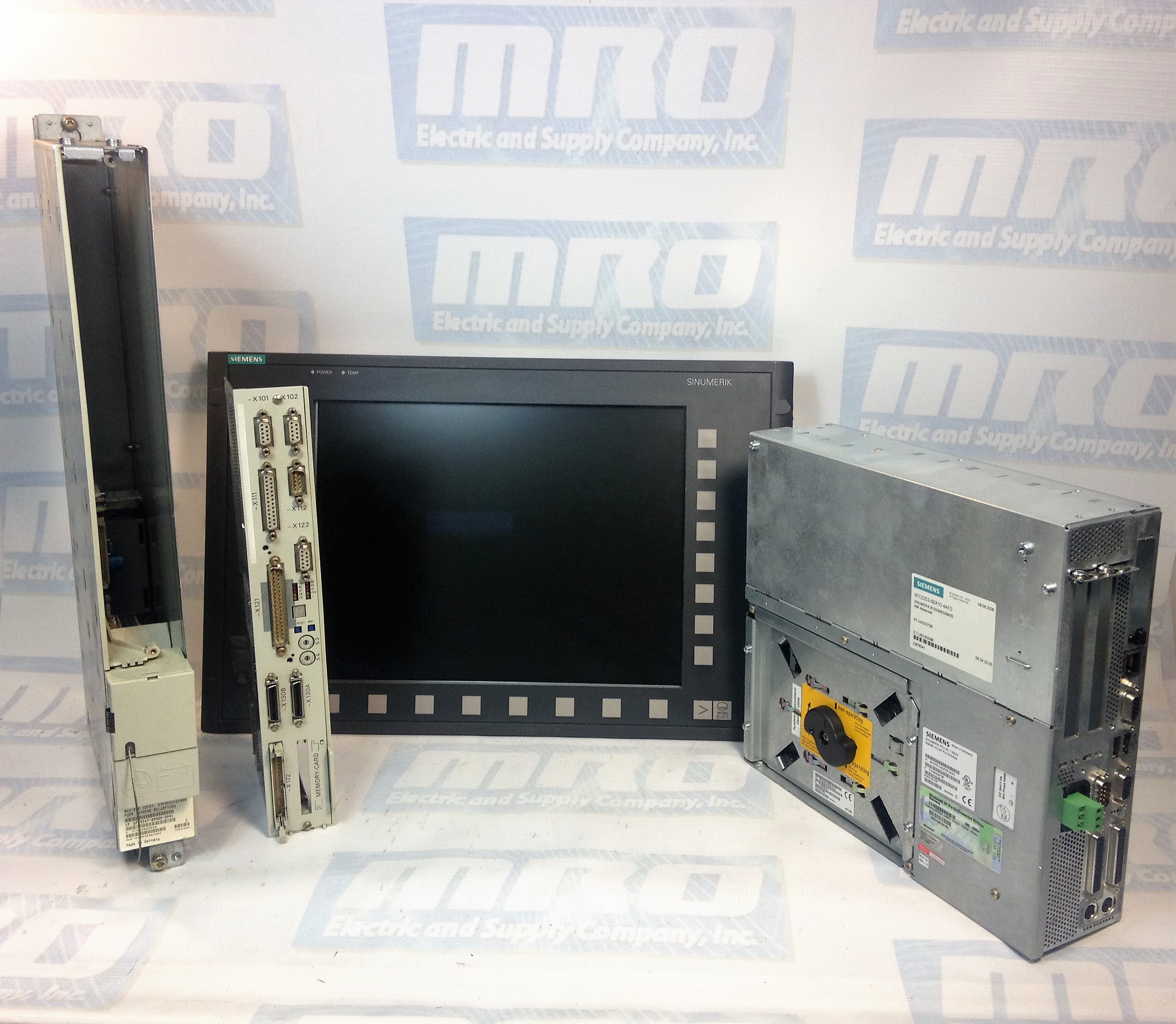
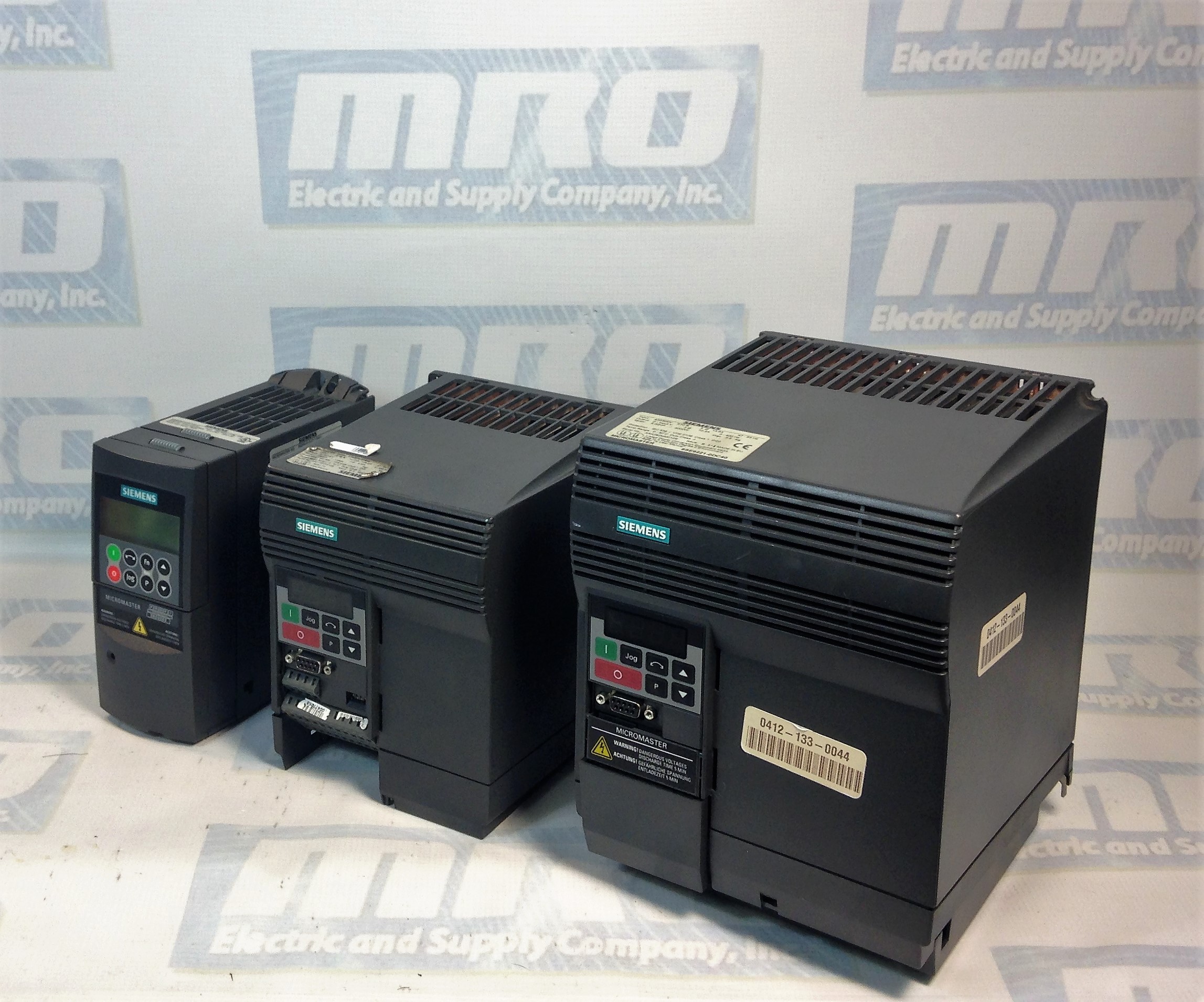
MRO Electric has new and refurbished Micromaster 440 Drives in stock. Take a look at all of our Siemens products including motors, drives, HMIs, and much more. Be sure to check out our list of Siemens Micromaster 420 fault codes as well.
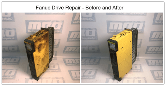
If you need assistance with your Micromaster 440, our team can also repair non-functioning drives. To request a quote, please email sales@mroelectric.com or call 800-691-8511.
Micromaster 440 Parameter List
Following parameters are needed for quick commissioning of a Micromaster 440 drive.| No | Name | Access level | Cstat |
|---|---|---|---|
| P0100 | Europe / North America | 1 | C |
| P0205 | Inverter application | 3 | C |
| P0300 | Select motor type | 2 | C |
| P0304 | Motor voltage rating | 1 | C |
| P0305 | Motor current rating | 1 | C |
| P0307 | Motor power rating | 1 | C |
| P0308 | Motor cosPhi rating | 2 | C |
| P0309 | Motor efficiency rating | 2 | C |
| P0310 | Motor frequency rating | 1 | C |
| P0311 | Motor speed rating | 1 | C |
| P0320 | Motor magnetizing current | 3 | CT |
| P0335 | Motor cooling | 2 | CT |
| P0640 | Motor overload factor [%] | 2 | CUT |
| P0700 | Selection of command source | 1 | CT |
| P1000 | Selection of frequency setpoint | 1 | CT |
| P1080 | Min. speed | 1 | CUT |
| P1082 | Max. speed | 1 | CT |
| P1120 | Ramp-up time | 1 | CUT |
| P1120 | Ramp-down time | 1 | CUT |
| P1135 | OFF3 ramp-down time | 2 | CUT |
| P1300 | Control mode | 2 | CT |
| P1500 | Selection of torque setpoint | 2 | CT |
| P1910 | Select motor data identification | 2 | CT |
| P3900 | End of quick commissioning | 1 | C |
Micromaster 440 Faults and Alarms
In the event of a failure, the inverter switches off and one of the following fault codes appear on the display.| Fault | Possible Causes | Diagnose & Remedy | Quit |
|---|---|---|---|
| F0001 OverCurrent | - Motor power (P0307) does not correspond to the inverter power (r0206) - Motor lead short circuit - Earth faults | Check the following: 1. Motor power (P0307) must correspond to inverter power (r0206). 2. Cable length limits must not be exceeded. 3. Motor cable and motor must have no shortcircuits or earth faults 4. Motor parameters must match the motor in use 5. Value of stator resistance (P0350) must be correct 6. Motor must not be obstructed or overloaded - Increase the ramp time - Reduce the boost level | OFF2 |
| F0002 OverVoltage | - DC-link voltage (r0026) exceeds trip level (P2172) - Overvoltage can be caused either by too high main supply voltage or if motor is in regenerative mode. Regenerative mode can be cause by fast ramp downs or if the motor is driven from an active load. | Check the following: 1. Supply voltage (P0210) must lie within limits indicated on rating plate . 2. DC-link voltage controller must be enabled (P1240) and parameterized properly. 3. Ramp-down time (P1121) must match inertia of load. 4. Required braking power must lie within specified limits. NOTE: Higher inertia requires longer ramp times; otherwise, apply braking resistor. | OFF2 |
| F0003 UnderVoltage | - Main supply failed. - Shock load outside specified limits. | Check the following: 1. Supply voltage (P0210) must lie within limits indicated on rating plate. 2. Supply must not be susceptible to temporary failures or voltage reductions. | OFF2 |
| F0004 Inverter Over Temperature | - Inverter overloaded. - Duty cycle too demanding. - Motor power (P0307) exceeds inverter power capability (r0206). | Check the following: 1. Load duty cycle must lie within specified limits. 2. Motor power (P0307) must match inverter power (r0206) | OFF2 |
| F0011 Motor Over Temperature | - Motor overloaded | Check the following: 1. Load duty cycle must be correct 2. Motor nominal overtemperatures (P0626-P0628) must be correct 3. Motor temperature warning level (P0604) must match | OFF1 |
| F0012 Inverter temp. signal lost | Wire breakage of inverter temperature (heatsink) sensor | OFF2 | |
| F0015 Motor temperature signal lost | Open or short circuit of motor temperature sensor. If signal loss is detected, temperature monitoring switches over to monitoring with the motor thermal model. | OFF2 | |
| F0020 Mains Phase Missing | Fault occurs if one of the three input phases are missed and the pulses are enabled and drive is loaded | Check the input wiring of the mains phases | OFF2 |
| F0021 Earth fault | Fault occurs if the sum of the phase currents is higher than 5 % of the nominal inverter current. NOTE - Framesizes D to F This fault only occurs on inverters that have 3 current sensors. | OFF2 | |
| F0022 Powerstack fault | That hardware fault (P0947 = 22 and P0949 = 1) caused by the following events: (1) DC-link overcurrent = short circuit of IGBT (2) Short circuit of chopper (3) Earth fault (4) I/O board is not poperly inserted. - Framesizes A to C (1),(2),(3),(4) - Framesizes D to E (1),(2),(4) - FramesizeF(2),(4) - Since all these faults are assigned to one signal on the power stack, it is not possible to establish which one actually occurred. - UCE failure was detected, when P0947 = 22 and fault value P0949 =12 or 13 or 14, depending on UCE (for MegaMaster only) | Check the I/O board. It has to be fully pressed home. | OFF2 |
| F0023 Output fault | One phase of output is disconnected | OFF2 | |
| F0024 Rectifier Over Temperature | - Ventilation inadequate - Fan inoperative - Ambient temperature is too high. | Check the following: - Fan must turn when inverter is running - Pulse frequency must be set to default value - Ambient temperature could be higher than specified for the inverter | OFF2 |
| F0030 Fan has failed | Fan no longer working | - Fault cannot be masked while options module (AOP or BOP) is connected. - Need a new fan. | OFF2 |
| F0035 Auto restart after n | Auto restart fault after n-restart try | OFF2 | |
| F0040 Automatic Calibration Failure | MICROMASTER 440 only | OFF2 | |
| F0041 Motor Data Identification Failure | Motor data identification failed. - Alarm value =0: Load missing - Alarm value =1: Current limit level reached during identification. - Alarm value =2: Identified stator resistance less than 0.1% or greater than 100%. - Alarm value =3: Identified rotor resistance less than 0.1% or greater than 100%. - Alarm value =4: Identified stator reactance less than 50% and greater than 500% - Alarm value =5: Identified main reactance less than 50% and greater than 500% - Alarm value =6: Identified rotor time constant less than 10ms or greater than 5s - Alarm value =7: Identified total leakage reactance less than 5% and greater than 50% - Alarm value =8: Identified stator leakage reactance less than 25% and greater than 250% - Alarm value =9: Identified rotor leakage inductance less than 25% and greater than 250% - Alarm value = 20: Identified IGBT onvoltage less than 0.5 or greater than 10V - Alarm value = 30: Current controller at voltage limit - Alarm value = 40: Inconsistence of identified data set, at least one identification failed Percentage values based on the impedance Zb = Vmot,nom / sqrt(3) / Imot,nom | 0: Check that the motor is connected to the inverter. 1-40: Check if motor data in P304-311 are correct. Check what type of motor wiring is required (star, delta). | OFF2 |
| F0042 Speed Control Optimisation Failure | - Motor data identification failed. - Alarm value =0: Time out waiting for stable speed - Alarm value =1: Inconsistent readings | OFF2 | |
| F0051 Parameter EEPROM Fault | - Read or write failure while saving nonvolatile parameter. | - Factory Reset and new parameterization - Change drive | OFF2 |
| F0052 power stack Fault | - Read failure for power stack information or invalid data | - Change drive | OFF2 |
| F0053 IO Eeprom Fault | - Read failure for IO EEPROM information or invalid data. | - Check data - Change IO module | OFF2 |
| F0054 Wrong IO Board | 1. Wrong IO board is connected. 2. No ID detected on IO board, No data. | - Check data - Change IO module | OFF2 |
| F0060 Asic Timeout | - Internal communications failure | - If fault persists, change inverter | OFF2 |
| F0070 CB setpoint fault | - No setpoint values from CB (communication board) during telegram off time | - Check CB and communication partner | OFF2 |
| F0071 USS (BOP-link) setpoint fault | - No setpoint values from USS during telegram off time | - Check USS master | OFF2 |
| F0072 USS (COMM link) setpoint fault | - No setpoint values from USS during telegram off time | - Check USS master | OFF2 |
| F0080 ADC lost input signal | - Broken wire - Signal out of limits | OFF2 | |
| F0085 External Fault | - External fault triggered via terminal inputs | - Disable terminal input for fault trigger. | OFF2 |
| F0090 Encoder feedback loss | - Signal from Encoder lost | 1. Check encoder fitted. If encoder not fitted, set P400 = 0 and select SLVC mode (P1300 = 20 or 22) 2. Check connections between encoder and inverter 3. Check encoder not faulty (select P1300 = 0, run at fixed speed, check encoder feedback signal in P66) Increase encoder loss threshold in P492 | OFF2 |
| F0101 Stack Overflow | - Software error or processor failure | - Run self test routines | OFF2 |
| F0221 PID Feedback below min. value | - PID Feedback below min. value P2268 | - Change value of P2268.Adjust feedback gain. | |
| F0222 PID Feedback above max. value | - PID feedback above max. value P2267. | - Change value of P2267.Adjust feedback gain. | |
| F0450 BIST Tests Failure | Fault value: 1. Some power section tests have failed 2. Some control board tests have failed 4. Some functional tests have failed 8. Some IO module tests have failed. (MM 420 only) 16. Internal RAM failed on power-up check | - Drive may run but some features will not work properly. - Replace drive. | |
| F0452 Belt Failure Detected | - Load conditions on motor indicate belt failure or mechanical fault. | Check the following: 1. No breakage, seizure or obstruction of drive train. 1. If using an external speed sensor, check for correct function.Check parameters: - P0409 (pulse per min at rated speed). - P2191 (Belt failure speed tolerance). - P2192 (delay time for permitted deviation) 2. If using the torque envelope, check parameters: - P2182 (threshold frequency f1) - P2183 (threshold frequency f2) - P2184 (threshold frequency f3) - P2185 (upper torque threshold 1) - P2186 (lower torque threshold 1) - P2187 (upper torque threshold 2) - P2188 (lower torque threshold 2) - P2189 (upper torque threshold 3 - P2190 (lower torque threshold 3) - P2192 (delay time for permitted deviation) 4. Apply lubrication if required. |
Need help with your Micromaster 440 drive?
Navigate through complex Micromaster 440 parameters and fault codes with ease. MRO Electric offers comprehensive support, from detailed parameter lists to expert repair services, ensuring your drive operates at peak performance.