Emerson Industrial Automation: Unidrive SP Troubleshooting
Updated August 2019: Click here to view Unidrive fault codes.
DIGITAL INPUTS
The Unidrive SP can be enabled to run in several ways. The drive can use digital inputs, keypad, or a field buss networks to give the OK to run. The drive will display inh, rdy, or run depending on the given commands. The drive can be programmed to use positive or negative logic. The logic type is set up at #8.29 in the Control Techniques Unidrive SP. The Unidrive SP defaults to positive logic. When the drive is in positive logic you will need to inject +24VDC to activate the digital inputs. The +24VDC can be supplied by the drive or externally.
The Unidrive SP can be enabled to run in numerous ways.
When the drive is in the terminal mode the following sequence occurs under default conditions:
Unidrive SP:
Inh = Drive disabled = Connect pins 22-31 drive should go to rdy
Rdy = Drive enabled = Connect pins 22-26 drive should go to run
Run = Drive is enabled and ready to run when a speed reference is applied
Parameter #0.05 sets up the Reference Select. This will tell the drive where to search for run commands and speed references. You will only need to close the enable signal if it is set to pad. Then, the keypad can be used to control the drive and to set the speed reference. The speed reference will come in on an analog input if you choose a terminal code. The digital inputs will select the enable, run, and preset selections. The drive should operate as seen above if the digital inputs are activated correctly.
DRIVE SEQUENCER
When the drive is not running, there are several additional parameters in menu 6 that can assess the issue. The digital inputs may be configured wrong or inactive if the parameters are not going to a 1 with the corresponding commands. Check the following parameters:
#6.15 = 1 = Drive enabled
#6.43 = 1 = Control word disabled, Set to 1 for Field Buss Control
#6.29 = 1 = Hardware Enable (Pin 31 is activated)
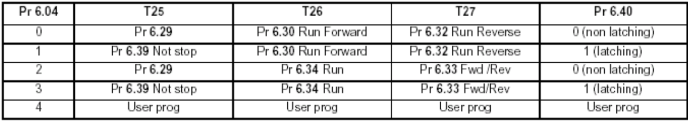
#6.30 = 1 = Run Forward #6.31 = 1 = Jog
#6.32 = 1 = Run Reverse
#6.33 = 1 = Forward/Reverse
#6.34 = 1 = Run
#6.37 = 1 = Jog Reverse
#6.39 = 1 = Not Stop
The voltage on the corresponding digital inputs should be measured if the parameters in menu 6 aren’t changing state accordingly. The DC voltage should change between 0VDC and 24VDC when a command is given. Check the digital input configuration in menu 8 if menu 6 isn’t changing and the voltage is.
CONTROL WORD
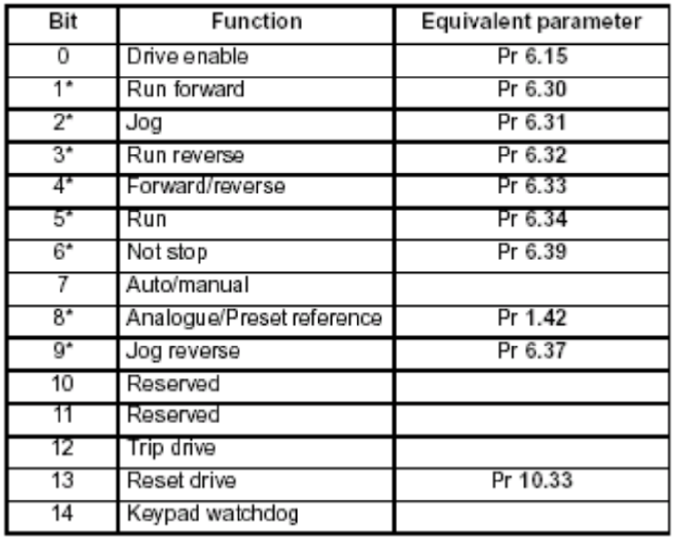
To control the start/stop functions, the drive does not have to use the digital inputs. When #6.43 = 1 the control word is enabled. The drive will now accept a decimal value from 0 to 32767 at #6.42. This decimal value can be converted to a binary value.To see the function that will be carried out, you can reference the binary value to the chart below.
Speed Reference
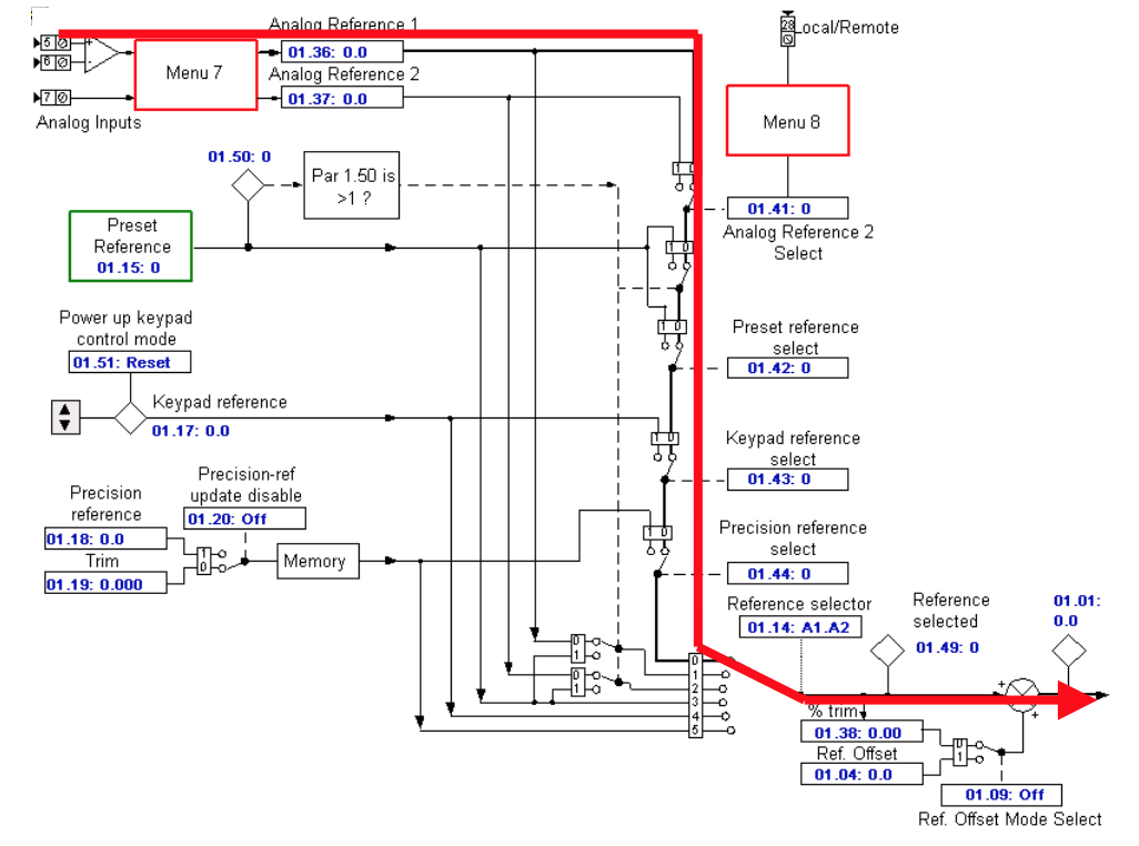
The drive still may not run if the digital inputs and the drive sequencer are each working properly. There could be an issue with the speed reference to the drive if the display shows Run but the motor isn’t turning. The speed reference is able to be applied in several methods. An analog input can be used (current or voltage), preset speeds, and a field buss reference. The example is a 0-10VDC signal on analog input #1.
The final speed of the demand is parameter #3.01. The speed reference should be displayed here if the digital inputs and the drive sequencer are failing to operate properly. Check menu 1 and 2 to determine where it is stopping if the reference is not getting to this point.
If the drive is running in torque mode, the torque reference will come on parameter #4.08 under default conditions. #4.08 is able to be linked to an analog input or be written to via a filed buss network.
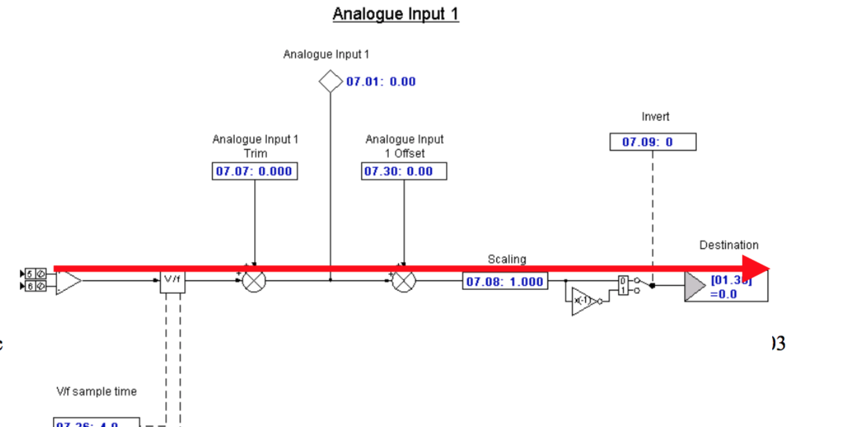
#7.01 should be inspected to determine if it changes with the change in reference at terminal 5 once the signal has been confirmed. #7.01 goes from +/- 0% – 100%. Check the destination of the speed reference at #7.10 if everything looks good. Follow it to the destination and confirm the speed reference value is arriving there and then through #3.01.
Contact the America’s Service Center if the drive will still not run after the Speed Reference, Digital Inputs and Drive Sequencer have all been confirmed.