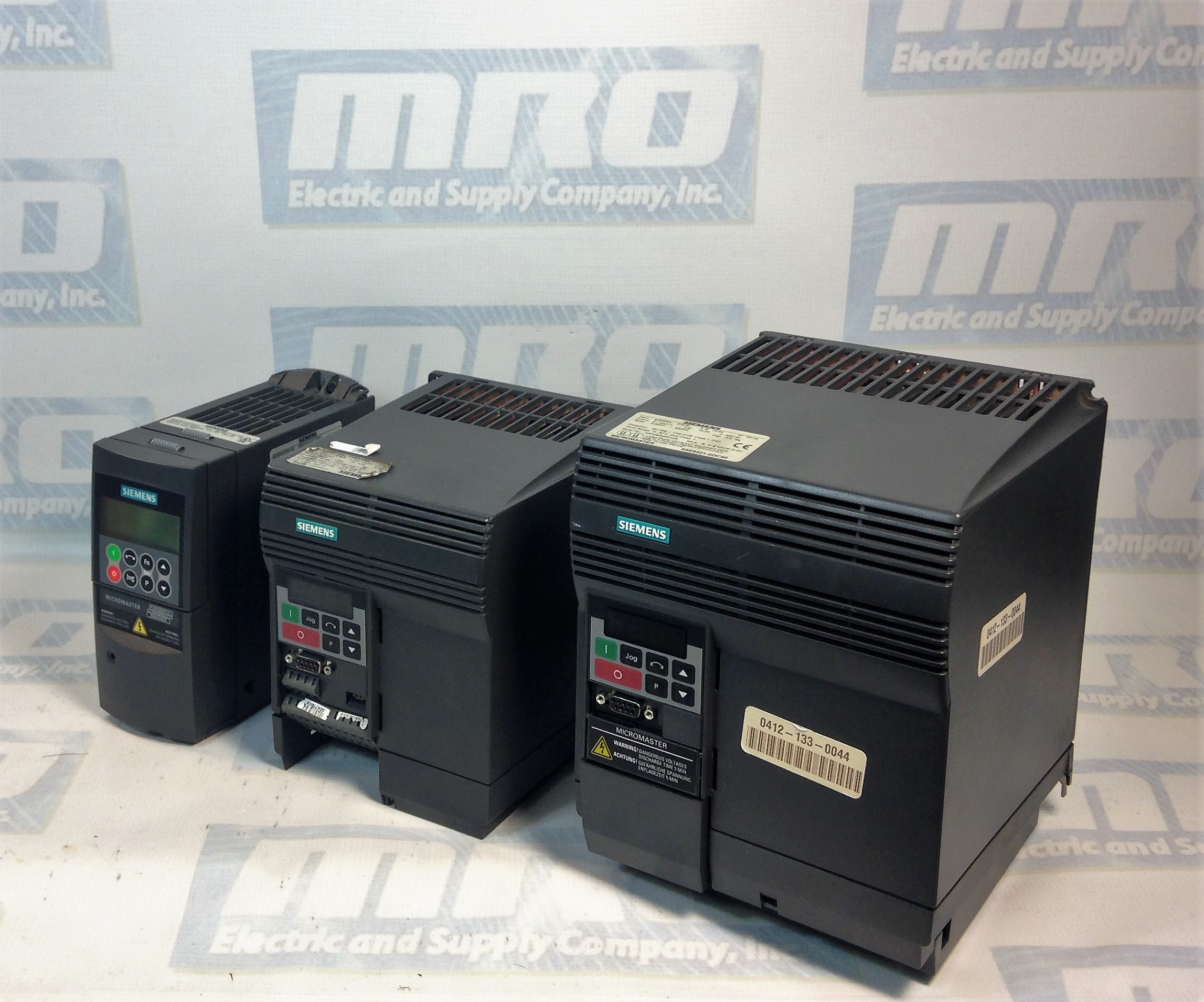
Micromaster 420

Siemens Micromaster 420 Troubleshooting Tips

Often people have difficulty installing a replacement drive that we send out, and normally it just takes the troubleshooting tips from the manual to get them up and running. However, the manual isn’t always the easiest to find or sort through, so below we’re posting the Siemens Micromaster 420 Troubleshooting section from the manual which should help anyone who is working to get the issues with their drive sorted out.

MRO Electric supplies and repairs Micromaster 420 Drives. To request a quote for a repair or spare, please call 800-691-8511 or email sales@mroelectric.com.

Read More

Updated on June 26, 2019 by Ryan Dickinson

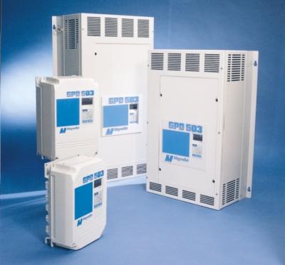
Yaskawa GPD 503 Drives

Installation of Yaskawa GPD 503 Drives:

1. Be certain your input voltage source, motor, and drive name plates are all marked either 230V, 460V, or 575V. Other voltages can be used, but they require additional programming.

2. Mount drive on vertical surface with adequate space for air circulation.

3. Remove front cover, fit conduit to bottom plate, and connect power and ground wires.

Caution: Be certain you connect power to terminals L1, L2, and L3 only, or serious damage will result. Connect motor to T1, T2, and T3 only.


Installation of External Run/Stop Switch and Speed Potentiators:

Important: Complete the Installation and Keypad Operation before attempting external control.

  1. Disconnect power, remove cover, and wait for “CHARGE” light to go out.
  2. Connect a switch to terminals 1 and 11 using two conductor shielded wire. This circuit is 24Vdc, very low current; use a quality rotary or toggle switch (all wire should be 14-18AWG). Connect the shield to terminal 12 on the drive end only.
  3. Install a single conductor “jumper wire” between drive terminals 5 and 11.
  4. Connect a manual speed potentiometer rated 2000-3000 ohms, 1 watt minimum, using three conductor shielded wire, with shield connected at terminal 12. Connect wires to the potentiometer. Trace wire closest to the top and connect to terminal 17. Trace center wire of potentiometer through and connect to terminal 16. The remaining wire will be connected to the trim pot in step 5.
  5. Connect a trim potentiometer rated 2000-3000 ohms, 1 watt minimum, as close to the drive terminals as possible. Viewing the potentiometer from the back, connect a single conductor wire from the left terminal to terminal 15 of the drive. Connect a short jumper wire between the center and left terminals. Connect remaining wire from manual speed pot as shown.
    Check out our other Yaskawa products, including GPD-505 and GPD-506 drives!
    MRO Electric and Supply Company carried new and remanufactured Yaskawa GPD 503 Drives. To place an order or for more information, call 800-691-8511 or email sales@mroelectric.com.

    Yaskawa GPD 503 Drives
    Yaskawa GPD 503 Drives

Updated on March 5, 2020 by Brian Hughes
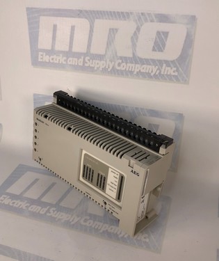
TSX PLCs – Compact, Flexible, Cost-Effective

TSX PLCs
TSX Nano PLCs are easy to set up and have numerous built in functions, such as memory for storing programs, battery-backed RAM, and real-time clocks for modules with 16 and 24 I/O’s. They can be installed easily on a mounting rail or base plate in the vertical or horizontal position. TSX PLCs are programmed in lists of instructions using the FTX 117 programming terminal, in Ladder or Instruction list language using software on an FT 2000, FTX 517 terminal or PC compatible. They can be used to augment extendable TSX PLCs using a single extension per base. Depending on the model they have

16 I/O : 9 inputs + 7 outputs
24 I/O : 14 inputs +10 outputs.

The following types of inputs and outputs are used:

Inputs : 24 Volts
Outputs : Relay outputs for models with ~ 100… 240 Volt power supply, transistor outputs with positive logic for models with 24 Volt power supply.

I/O Extension

Each TSX Nano base PLC can be extended using an I/O extension. This extension is created by one of the PLCs with 10, 16, or 24 i/o. The function of each PLC is defined by the position of the coding selector switch:
Position 0 : base PLC
Position 1 : I/O extension

Peer PLCs

Up to 3 peer TSX PLCs, communicating via common words, can be connected to the base PLC. In this case, only the base PLC can receieve an I/O extension. The function of each PLC is defined by the position of the coding selector switch. I/O addressing of peer PLCs is identical to that of the base TSX PLC. The extension link cable between the base PLC and PLC extensions is shielded, twisted pair  and is no more than 200 meters long.  Each PLC has 2 reserved (IW) and 2 reserved (QW) words for exchanging data between PLCs. These exchange words are updated automatically. For each PLC, the user program is only able to write to the 2 %QW output words and read the 2 %IW input words.

MRO has many Modicon PLCs available. For more information, please email sales@mroelectric.com or call 1-800-691-8511.

Updated on March 5, 2020 by Brian Hughes