Checking the Simodrive Power Section

Ohm Checking the Simodrive Power Section
Caution!  It must be assured that power is removed and the DC Bus has drained to a safe level before any connections are removed or checked!

Check out our website for all Siemens and Simodrive products.

After you are sure that the DC Bus has safely discharged , a DVM on the Diode scale can be used to detect if a  short circuit or open exists in the power section.  Readings will vary with module size.

Note:   P600 and M600 are the 600 V DC Bus connections.  U2, V2 and W2 are the motor connections.

• Disconnect the P600, M600 bus bars, U2, V2 and W2 connections.  This isolates the power module from the motor and DC Bus.
• Diode check between P600 and U2, then V2 then W2. There should be continuity with the – lead on P600 and the + lead on U2, V2 or W2.  Readings should be open with the leads reversed.
• Diode check between M600 and U2, V2, W2.  There should be continuity with the + lead on M600 and the – lead on U2, V2 or W2.  Readings should be open with the leads reversed.
• Diode check between P600 and M600.  There should be continuity with the + lead on the M600 and the – lead on P600.  The reading should be open with the leads reversed.
• Diode check between U2, V2 and W2.  All combinations should read open.

Note:  If all readings are open the internal DC Bus fuse is open.  If there is a 0Ω reading, there is a  short in the power circuit.
Note 2: Because of the capacitance in the power circuit, resistance checks will indicate a charging effect.  It is necessary to wait until the measurement has stabilized to determine if it is correct.  If possible, it is best to use a DVM with a diode check.

For more info you can visit our website to see all our Siemens Simodrives or email sales@mroelectric.com.

Updated on May 20, 2019 by Brian Hughes

Modicon Quantum PLC Overview

The Modicon Quantum PLCs provide well-balanced CPUs able to provide leading performance from boolean to floating-point instruction.

  • Unity Pro programming software supports five IEC languages as standard: IEC Ladder (LD), Structured Text (ST), Function Block Diagram (FBD), Sequential Function Chart (SFC), and Instructional List (IL), as well as the Modicon LL984 language to facilitate installed base upgrades.
  • High-level multitasking system
  • Memory capacity up to 7 Mb using Personal Computer Memory Card International Association(PCMCIA) extensions.
  • Specially designed for process control applications with conformal coated modules and an extensive catalogue of partner modules
  • Safety processors and I/O modules to manage Safety Instrumented Systems (SIS).
  • Plug & Play high-performance Hot-Standby solutions with LCD keypad for local monitoring
  • Adheres to open standards for communications including Ethernet Modbus® TCP/IP, EtherNet/IP (the new ODVA standard for EtherNet/IP™ incorporates Modbus TCP/IP), Profibus and others.
  • Numerous built-in ports (USB port, Ethernet TCP/IP port with Web server, Modbus Plus and at least one Modbus serial port) on the front panel
  • In-rack connectivity to Profibus® DP
  • Embedded Ethernet Router
  • Increase the availability of your architecture by using Quantum Ethernet I/O modules (QEIO) that support deterministic Remote I/O (RIO)
  • The Modicon X80 I/O expands your architecture and easily integrates your distributed devices in the same network (such as HMI, variable speed drives, I/O islands…)
  • Supports the Highway Addressable Remote Transducer (HART), the protocol for sending and receiving digital information across analog wires between smart devices and a control or monitoring system

Choose performance
Offering a large range of processors, Modicon Quantum is ideal for complex processes. The power of its processors results in optimum cycle times, while integrating even more communication functions, diagnostics, memory flexibility and data storage. The Quantum Safety system is now available, certified by TÜV Rheinland, simple to use and ready to be integrated in your automated system.

More flexibility
Choose the best topology, daisy chain loop, ring, star, bus… for the design of your Ethernet architecture.

Higher availability
Hot-standby CPUs and daisy chain loop topology improve the availability of your process. In the event that the cable is broken, the recovery time is less than 50 ms for an entire Quantum Ethernet I/O architecture.

Visit our website for more information on Modicon Quantum modules or email sales@mroelectric.com.

Updated on March 5, 2020 by Brian Hughes

Modicon Momentum PC Based PLCs

Modicon Momentum PLC
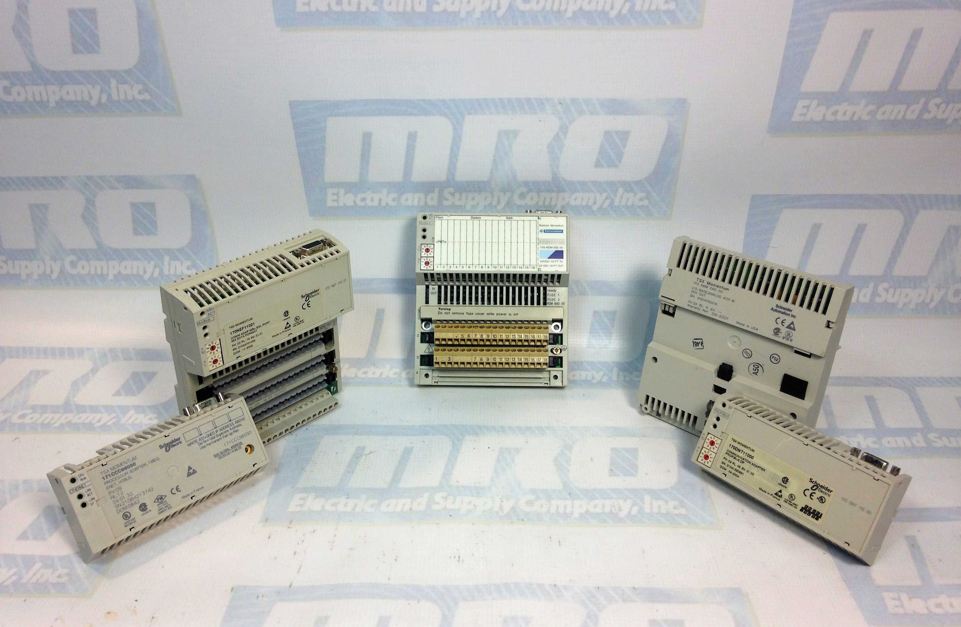
The small footprint and open architecture of the Modicon Momentum PLC product line make it extremely versatile for a variety of Unity™ Pro automation applications. Modicon Momentum PLC options and accessories include: I/O bases, processor adapters, option adapters and communication adapters that are interchangeable and snap together to deliver optimal flexibility throughout the control system life cycle.

The Modicon Momentum PLC offers:

  • IP 20 Monoblock I/O bases which provide the foundation for the rest of the Modicon Momentum control system and serve as the mounting base for communication adapters and processors. Over 30 I/O module types available: Analogue, Discrete, Multi-function, etc.
  • Processor Adapters:
    • Operate with a single local I/O module or in systems with up to 32 I/O modules
    • Built-in communication ports including, Ethernet Modbus™ TCP/IP or Modbus RS232/RS485 serial communication, USB and IO Bus
    • Perform functions including data acquisition, peer-to-peer communication, and I/O scanning. Embedded web pages enable the use of a standard web browser to read status and diagnostic information from the processor.
  • Communication Adapters snap into any of the I/O modules and include Modbus TCP/IP, Modbus™ Plus, FIPIO™, INTERBUS™, and PROFIBUS® DP.
  • The Modicon Momentum PLC also offers selected I/O bases, processors, and communication modules with conformal coating – ideal for applications with harsh or humid environments that require a small footprint.

Modicon Momentum Unity CPU
The Modicon Momentum Unity™ CPU allows the simple upgrade that helps you increase the capacity and efficiency of your legacy Modicon Momentum application in a cost-effective way. The Modicon Momentum Unity CPU enables you to standardize and manage your controllers on a single programming software, Unity Pro software. It delivers a low-cost and low-risk modernization path while protecting your previous investment.

Why you should modernize now.
Upgrading to the Modicon Momentum Unity CPU is the simplest modernization strategy for your legacy PLCs. Unite all your small, medium, and large controllers on the Unity Pro software platform with robust communications and state-of-the-art programming functions

  • Cost-effective – Preserve the existing Momentum I/O investment and import developed Modsoft™, Proworx™, or Concept™ application programs
  • Simple – Upgrade to a single, intuitive software suite to manage all controllers
  • Ready for the future – Embark on a clear path for future modernization with PlantStruxure integrated architecture

For more information on Modicon Momentum modules, please call 800-691-8511 or email sales@mroelectric.com.

modicon momentum
Modicon Momentum Modules

Updated on June 26, 2019 by Ryan Dickinson

Fanuc Motor Safety Procedures and Tips

We have people ask about best practices for working with Fanuc motors all the time, so here are some Fanuc Motor Safety Procedures and Tips. For more info you can check out  all of our Fanuc products or email us at sales@mroelectric.com.
When working with servo motors:
•NEVER pick up or carry the motor by the cables or the shaft. (Always carry by the frame.) Use a crane or lift to move the motor when necessary.
•NEVER drop or subject the motor to impact. The servo motor is a precision device.
•NEVER set heavy or sharp objects on the motor or cables. Do not step or sit on the motor or cables.
•NEVER use a metal hammer on any part of the motor. If it is absolutely necessary to use a hammer, use a plastic hammer.
Keep the motor properly secured and away from the edge of the work area when servicing the motor, as a dropped motor could

cause personal injury or destroy the motor

Basic Motor Safety, Procedures, and Best Practices
• Be safely dressed when handling a motor.
Wear safety shoes and gloves. Avoid loose clothing which can get caught
on the motor. Be careful not to let hair get caught in the rotary section of the motor. Do not handle the motor with wet hands.
• Shut off the power before working on a motor. Wait at least 5 minutes after the motor is shut off before touching any
power terminals.
• Always use the correct cables. Centroid cables are shown in the motor compatibility table. Wiring diagrams and pin outs
for motors are provided in Appendix B.
• Ensure that the motor and motor related components are mounted securely. Ensure that the base or frame to which the
motor is mounted to is strong enough.
• Do not touch the rotary section of the motor when it is running unless instructed to.
• When attaching a component having inertia to the motor, ensure any imbalance between the motor and component is minimized.
• Be sure to attach a key to a motor with a keyed shaft.
• Use the motor in appropriate environmental conditions. Do not store flammables in close proximity to the motor. When
not in use, store the motor in a dry location between 0° to 40° C.
• Do not remove the nameplate from a motor

Updated on May 20, 2019 by Brian Hughes

Timeline, CPUs and Programming of the Modicon PLC Series

The Modicon PLC Series has been around for almost 40 years at this point, from the 484 series to the M340 series. The timeline below lists the CPU part numbers, the years they were sold, and what they are programmed with. For more info you can visit our series page here or email sales@mroelectric.com.

Modicon 484
CPU Part Number: AS-C484-xxx
Actively Sold: 1977-1983
Programmed With: P190 programmer

Modicon 584
CPU Part Number: AS-584A-xxx, AS-584M-xxx, AS-584L-xxx
Actively Sold: 1979-1984
Programmed With: Modsoft, ProWorx Plus/Nxt/32 Software

Modicon 984 Chassis Mount
CPU Part Number: P1-984X-008, Px-984A-xxx, Px-984B-xxx
Actively Sold: 1985-1999
Programmed With: ProWorx Plus/Nxt/32 and Modsoft Software

Modicon 984 Slot Mount
CPU Part Number: PC-A984-3xx, PC-D984-xxx, PC-K984-xxx
Actively Sold: 1987-2006
Programmed With: ProWorx Plus/Nxt/32 and Modsoft Software

Modicon Compact 984
CPU Part Number: PC-A984-xxx, PC-E984-2xx
Actively Sold: 1991-2007
Programmed With: Modsoft, ProWorx Plus/Nxt/32, Concept software

Modicon Micro
CPU Part Number: 110CPU311xx, 110CPU411xx, 110CPU512xx, 110CPU612xx
Actively Sold: 1996-2006
Programmed With: Modsoft, ProWorx Plus/Nxt/32 software

Modicon Quantum
CPU Part Number: 140CPUxxxxx
Actively Sold: 1994 to present
Programmed With: ProWorx 32, Concept, Unity software

Modicon Premium
CPU Part Number: TPCX57xxxx, TSXP57xxxx
Actively Sold: 1998 to present
Programmed With: PL7 or Unity software

Modicon Momentum
CPU Part Number: 171CCC7xxxx, 171CCS7xxxx, 171CCC9xxxx
Actively Sold: 1998 to present
Programmed With: ProWorx, Concept software

Modicon M340
CPU Part Number: BMXP341000, BMXP342010, BMXP342020, BMX342030
Actively Sold: 2007 to present
Programmed With: Unity V3.0 software

Updated on July 1, 2019 by Ryan Dickinson

Unidrive Security Code Basics

For some new User’s of Unidrives, the parameter security system is sometimes found to be a rather mysterious subject.  This article will attempt to unveil those mysteries with some help to explain the Control Techniques Unidrive Security Code Basics.

Security Basics

Without entering the basic security code, 149, you will only be able to view Menu 0 parameters.   The “as shipped” security code for the Unidrive is 149. To enter this code you would maneuver to #00.00 and enter 149.   Once this security code is entered, you will be able to maneuver throughout the Unidrive menu structure freely to view parameters.

After a security code is entered, it will remain in effect until power is removed from the drive or if you wish to re-establish this security, you can set  #XX.00 to 2000.  (where  XX means  “any menu”  )

The User Security Code parameter is #11.30.  The “as shipped” value in this parameter is 149.

For more info you can check our webpage here, or email sales@mroelectric.com or call 1-800-691-8511.

If you find that you cannot change R/W (Read/Write) parameters (including those in Menu 0), someone has most likely assigned their own security code.

User Security Code Assignment

User’s can assign their own 3 digit security code within the range of 1-255 by placing it into #11.30 (writing over the 149) and performing a STORE.1 Note that this does not eliminate or change the “Normal security” code number – 149.

From this point forth, access to parameters will require that code to be placed into #XX.00.  At this point you only have access to Menu O. After this code is entered, you must still enter the normal access code (149) to gain access beyond Menu 0 parameters ( full access).

These security methods do not affect serial communications.  Security affects only access to parameters through the keypad on the front of the Drive.

Forgotten Security Codes

People often forget their security codes.   A User assigned security code is not visible at #11.30 via the serial port (you would still see 149).  To retrieve the forgotten security code,  you must go in through the “back door” .

“The Back Door”

To obtain the forgotten security code, you can DEPRESS and HOLD the MODE key, LEFT ARROW key and either UP or DOWN Arrow key then APPLY POWER to the drive.   The User security code number should appear on the data display at #00.00. Normally, the drive displays the contents of parameter #0.10 upon application of power therefore the User security code may not immediately appear.  You must use maneuver to #00.00 to see the forgotten security code then enter it (hit the mode button twice).

Security Bypass 

During initial start-up of the drive, having to enter the security code after each power-up can become a nuisance and slow down the start-up process.   To bypass or eliminate the need to enter a security code, one can accomplish this by placing a 0 into parameter #11.30 and performing a Store.
If this bypass is done to speed up the start-up process, you should remember to re-assign the 149 default to #11.30 (and Store) before leaving the job site. Otherwise, the drive will have no parameter access security.
Note: Defaulting the drive parameters (using 1244 or 1254) does not reset the User security code.  A previously assigned code by the User will remain in effect even after defaulting parameters.

Additional information     

Parameter 0.49 Security Status
Coding:  RO, U Range:  0 to 1000
This parameter indicates the current status of the drive parameter security system. Each digit indicates a particular aspect of security as follows:-

Units digit:  0 = Standard security has been unlocked    1 = Standard security is still set

Tens digit:                0 = User security has been unlocked or is not active    1 = User security is active preventing RW access

Hundreds digit: 1 = Parameter 11.30 not equal to 149*

Thousands digit: 1 = Parameter 11.30 equal to zero*

* The value of 11.30 is the last value written by the user. Parameter 11.30 always appears as 149 when first accessed by the keypad to hide the real value last written by the user. If 11.30=149 then user security is cleared. If 11.30=0 then user security and security preventing access outside menu 0 is cleared.

Note: – In contrast to all the other parameters in menu 0, this parameter does not exist in any other menu.

Updated on March 5, 2020 by Brian Hughes

The Modicon 984 Family of PLCs

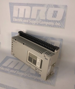
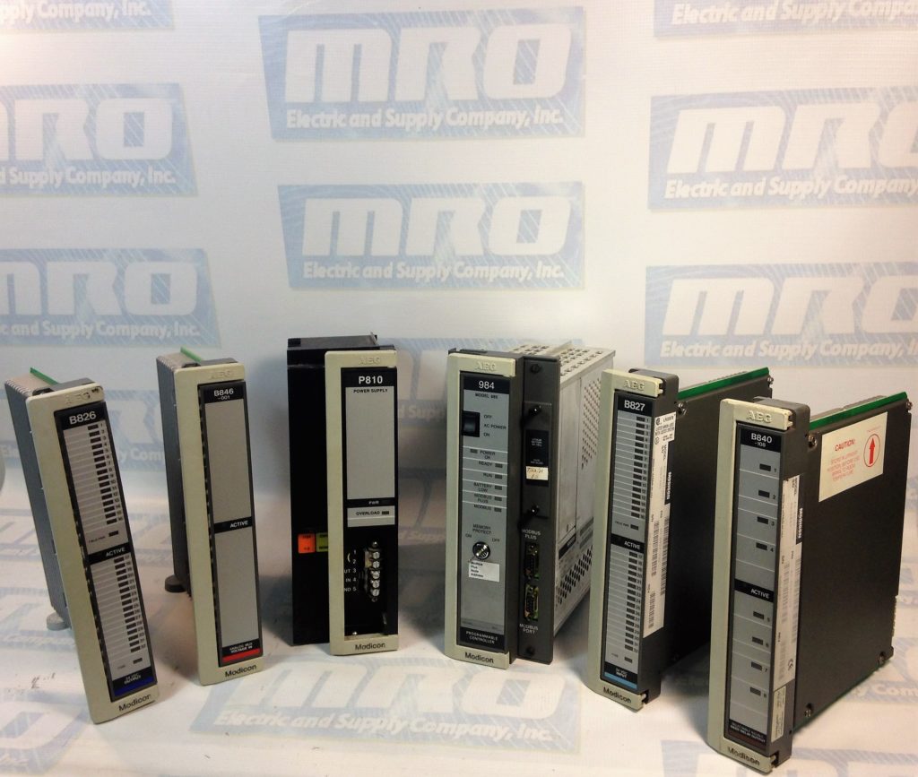
The Modicon 984 family of PLCs  bring the high performance,
application flexibility, and programming compatibility of the 984 family to the small
controller market. As a controller in the 984 family, Compacts implement a common
instruction set for developing user logic, standard Modbus communication
functionality, and optional Modbus Plus communication capabilities.
The Compact Controllers share the following 984 processing architecture features:
– A memory section that stores user logic, state RAM, and system overhead in
battery-backed CMOS RAM and holds the system’s Executive firmware in
nonvolatile PROM or FLASH RAM
– A CPU section that solves the user logic program based on the current input
values in state RAM, then updates the output values in state RAM
– An I/O processing section that directs the flow of signals from input modules to
state RAM and provides a path over which output signals from the CPU’s logic
solve are sent to the output modules
– A communications section that provides one or more port interfaces. These
interfaces allow the controller to communicate with programming panels, host
computers, hand-held diagnostic tools and other master devices, as well as with
additional controllers and other nodes on a Modbus (or Modbus Plus) network
 
This architectural consistency allows the The Modicon 984 Family of PLCs to achieve machine compatibility with the other controllers in the family. This allows sequences of user logic created on a mid-range or high performance controller, such as a 984B or a
984-685 Controller,-to be relocated to a Compact. It also assures that user logic
generated for this small controller is upwardly compatible to larger 984(s). Thus, a
Compact can be easily integrated into a multi-controller network.
 
For more info you can visit our web page here or call 1-800-691-8511 or you can even email sales@mroelectric.com.

Updated on March 5, 2020 by Brian Hughes