Fanuc Spindle Amp Alarm Codes for Alpha Series

fanuc spindle amp

Fanuc Spindle Amp Alarm Codes for Alpha Series

Fanuc Spindle Amp Alarm codes for amplifiers that start with part number A06B-6088, A06B-6102, and A06B-6078.

“A” Program Rom abnormality (Not Installed)

AL-01 Motor Overheat

AL-02 Excessive speed deviation

AL-03 DC Link fuse blown

AL-04 Input fuse blown

AL-05 Control power supply

AL-06 Over Speed

AL-07 Excessive Speed

AL-08 High Input Voltage

AL-09 Excessive load on main circuit section

AL-10 Low input voltage

AL-11 Over-voltage in DC link section

AL-12 Over-current in DC link section

AL-13 CPU Internal data memory abnormality

AL-15 Spindle switch/output switch alarm

AL-16 RAM Abnormality

AL-18 Program ROM checksum error

AL-19 Excessive U phase current detection circuit offset

AL-20 Excessive V phase current detection circuit offset

AL-24 Serial transfer data error

AL-25 Serial transfer data stopped

MRO Electric and Supply maintains a comprehensive stock of new and used FANUC CNC parts including FANUC Spindle Amps. If you need a replacement part, please call 800-691-8511 or email sales@mroelectric.com.

AL-26 Disconnection of speed detection signal for C’s contouring control

AL-27 Position coder signal disconnection

AL-28 Disconnection of position detection signals for C’s contouring control

AL-29 Short-time overload

AL-30 Input circuit over current

AL-31 Speed detection signal disconnection motor restraint alarm

AL-32 Abnormality in RAM internal to LSI for serial data transfer

AL-33 Insufficient DC link section charging

AL-34 Parameter data setting beyond allowable range of values

AL-35 Excessive gear ratio data setting

AL-36 Error counter overflow

AL-37 Speed detector parameter setting error

AL-39 Alarm for indicating failure in detecting 1-rotation signal for C’s contouring control

AL-40 Alarm for indicating 1-rotation signal for C’s contouring control not detected

AL-41 Alarm for indicating failure in detecting position coder 1-rotation signal

AL-42 Alarm for indication position coder 1-rotation not detected

AL-43 Alarm for indicating disconnection of position coder signal for differential speed mode

AL-46 Alarm for indicating failure in detecting position coder 1 rotation signal in thread cutting operation

AL-47 Position coder signal abnormality

AL-48 Position coder 1-rotation signal abnormality

AL-49 The converted differential speed is too high

AL-50 Excessive speed command calculation value in spindle synchronization control

AL-51 Under voltage at DC link section

AL-52 ITP signal abnormality 1

AL-53 ITP signal abnormality 2

AL-54 Overload current alarm

AL-55 Power line abnormality in spindle switching/output switching

AL-56 Cooling fan error.

Updated on March 5, 2020 by Brian Hughes
Emerson Commander SK Advanced User Guide & Manual

Struggling with troubleshooting and repair? Keep your equipment running smoothly by using the following guide to diagnose any trip codes. The following are some of the common errors you might encounter:

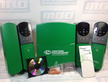
Emerson Commander SK Fault & Trip Codes by Control Techniques

Trip Code Condition Possible Cause
UU DC Bus under voltage Low AC Supply Voltage

Low DC Bus voltage when supplied by an external DC power supply

OU DC Bus over voltage Deceleration rate set too fast for the inertia of the machine

Mechanical load driving the motor

OI.AC** Drive output instantaneous over current Insufficient ramp times

Phase to phase or phase to ground short circuit on the drives output

Drive requires autotuning to the motor

Motor or motor connections changed, re-autotune drive to motor

OI.br** Braking Resistor instantaneous over current Excessive current in braking resistor

Braking resistor value to small

O.SPd Over Speed Excessive motor speed (typically caused by a mechanical load driving the motor
tunE Autotune stopped before completion Run command removed before autotune compelte
It.br I2t on Braking Resistor Excessive braking resistor energy
lt.AC l2t on drive output current Excessive Mechanical load

High impedance phase to phase or phase to ground short circuit at drive output

Drive requires re-autotuning to motor

O.ht1 IGBT over heat based on dries thermal model Over heat software thermal module
O.ht2 Over heat based on drives heatsink Heatsink temperature exceeds maximum allowable
th Motor thermistor trip Excessive motor temperature
O.Ld1* User +24v or digital output overload Excessive load or short circuit on +24v output
cL1 Analogue input 1 current mode, current loss Input current less than 3mA when 4-20 or 20-4mA modes selected
SCL Serial communication loss time-out Loss of communication when drive is under remote control
EEF Internal Drive EEPROM trip Possible loss of parameter values
PH Input phase imbalance or input phase loss One of the input phases has become disconnected from the drive (applies to 200/400v three phase drives only, not dual rated drives.
rS Failure to measure motors stator resistance Motor too small for drive

Motor cable disconnected during measurement

C.Err SmartStick data error Bad connection or memory corrupt within SmartStick
C.dAt SmartStick data does not exist New/empty SmartStick being read
C.Acc SmartStick read/write error fail Bad connection or faulty SmartStick
C.rtg SmartStick/drive rating change Already programmed SmartStick read by a drive of a different rating
O.cL Overload on current loop input Input current exceeds 25mA
HFxx trip Hardware faults Internal drive hardware fault

HF01 to HF03
Not used
HF04
Low DC bus at power up- may indicate an AC Input or pre-charge problem
HF05
No internal handshake signal from second processor (DSP) at start up
HF06
Unexpected interrupt
HF07
Watchdog failure
HF08
Interrupt crash (code overrun)
HF09 to HF10
Not used
HF11
Access to the EEPROM failed- tried to read stored parameter data but failed
HF12 to HF19
Not used
HF20
Power stage – code error Tried to read power board and read back erroneous
HF21
Power stage – unrecognized frame size
HF22
Overcurrent detection at power up- possible output short or bridge failure
HF23
DSP software overrun
HF24
Not Used
HF25
DSP Communications failure- communication from main to 2nd processor
HF26
Soft start relay failed to close; or soft start monitor failed; or braking
IGBT short circuit at power up
HF27
Power stage thermistor fault
HF28
Power circuit thermistor 2 or 3 fault Internal fan fault on size 3 only
HF29
Fan failure (current too high – only on drives with a fan) see note below
HF30
Not used
HF31
Internal Cap Bank Fan failure- check for fan rotation/blockage Size 4 and up
HF32
Power circuit temperature feedback multiplexer failure

Looking for more information about Control Techniques equipment? Read on here. 

Shopping for new or refurbished Control Techniques parts? Shop for the parts you’re looking for here, or find out more about how MRO Electric can help you repair your equipment

Experiencing Trip Codes on Your Commander SK?

Trip codes can be puzzling, but MRO Electric has the solution. Whether you need in-depth guides to understand your Commander SK drive’s codes or require immediate repair service, we’re here to support you in restoring your system’s efficiency swiftly.

Updated on March 26, 2024 by Joe Kaminski

Unidrive SP SM-EZ Motion HF Trips

Unidrive SP SM-EZ Motion HF Trips

This guide is meant to help clear SM-EZ Motion HF Trips on a Unidrive SP drive from Emerson Control Techniques. The SM-EZ motion module is used with SP drives and is programmed using Power Tools Pro. It allows users to create specific motion profiles such as indexing, home routines, electronic gearing, and many others.

An HF (hardware fault) can be generated by the drive if there is a problem with the solutions module. The drive will display the trip as SLX.HF. It is sometimes possible to correct this trip without replacing the module. The EZ Motion program in the module may become corrupt which can cause this type of trip. Clearing the program and setting the module back to factory settings may resolve the trip. Before clearing the module a drive reset and power cycle should be performed.

They could correct the trip as well.

unidrive sp
Module Clearing Procedure

1. Ensure the module is installed in any slot

2. Enter 19237 at #18.01

3. Cycle power to the drive

4. The drive will trip SLX.ER on power up. This is a 107 “No Program” trip

5. Press the red reset button to clear the SLX.ER trip

6. Reload your EZ Motion program back into the drive.

The HF trip could be resolved at this point.

MRO Electric supplies and repairs a large number of Control Techniques Unidrive SP parts. To request a quote, please call 800-691-8511 or email sales@mroelectric.com.

Updated on March 5, 2020 by Brian Hughes
Simodrive F15 Alarm Code – Cause and Solution

Recently a customer sent in a Siemens Simodrive for repair when they were getting an F15 Alarm on the unit. The description for this alarm is as follows:

– F–15 Drive converter
– Overtemperature
     – Drive converter overloaded
(incorrect motor/converter assignment, incorrect load duty cycle,
clock cycle frequency too high)
      – Ambient temperature too high
      – Fan in the IM module failed
      – Defective temperature sensor in the IM module

Normally, this Simodrive F15 Alarm is in reference to the fans in the unit failing, which in turn causes an over temperature issue in the unit. This is normally caused by the fans not being cleaned out regularly which causes them to jam, which can then short out other internal boards in the unit. This was the case for the unit the customer sent in, so we took apart the unit, replaced the fans, and replaced several internal boards that had shorted. We would highly recommend routine cleaning of Simodrive fans, especially dirty ones, to prevent drive failure.

MRO Electric and Supply supplies and repairs a large number of Siemens Simodrives. To request a quote, please call 800-691-8511 or email sales@mroelectric.com.

Updated on March 5, 2020 by Brian Hughes
Fanuc Alpha Power Supply Fault Codes

fanuc cnc

Fanuc Alpha Power Supply Fault Codes

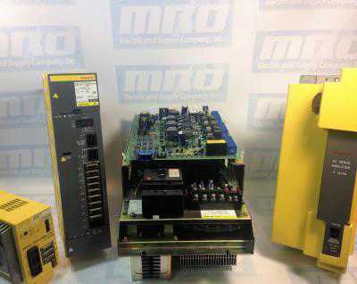
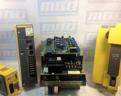
These codes and troubleshooting apply to DC and AC Fanuc power supplies that begin with part number A06B-6077, A06B-6081, and A06B-6087. On the LED display for these units, a “-” will mean that the power supply is not ready while a “0” means that the power supply is powered up correctly. If it reads something other than these two then the power supply has an alarm that needs to be corrected. Below is the list of Fanuc Alpha Power Supply fault codes.

MRO Electric and Supply maintains a comprehensive stock of new and used FANUC Spindle Amps. If you need a replacement part, please call 800-691-8511 or email sales@mroelectric.com.

Alarms
AL-01: Overcurrent in the Main Power Module.
AL-02: Cooling Fan Stopped.
AL-03: The temperature of the main circuit heat sink has risen abnormally.
AL-04: The DC Voltage has dropped.
AL-05: The main Capacitor was not recharged within the specified time.
AL-06: The Input Power Supply is Abnormal.
AL-07: In the main circuit the DC Voltage is abnormally high

A common alarm on installation of a new alpha power supply is an AL-05.
If you have this alarm we recommend double-checking the bus bar connector at the top of the power supply to make sure it is fully connected. Be sufe to check out our article on FANUC Alpha Servo Troubleshooting as well as  FANUC CNC parts.

Updated on March 5, 2020 by Brian Hughes
Testing a UNI1402 Unidrive

Testing a UNI1402 Unidrive

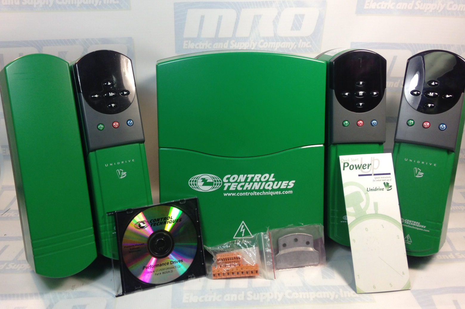
Video of part of the testing process for a UNI1402 Unidrive classic.

Be sure to check out our article covering details to maintain Unidrive Classic and Unidrive SP drives here.

MRO Electric and Supply maintains a comprehensive stock of new and used  Control Techniques Unidrive and Control Techniques Unidrive Classic SP parts. If you need a replacement part, please call 800-691-8511 or email sales@mroelectric.com.

Updated on March 5, 2020 by Brian Hughes
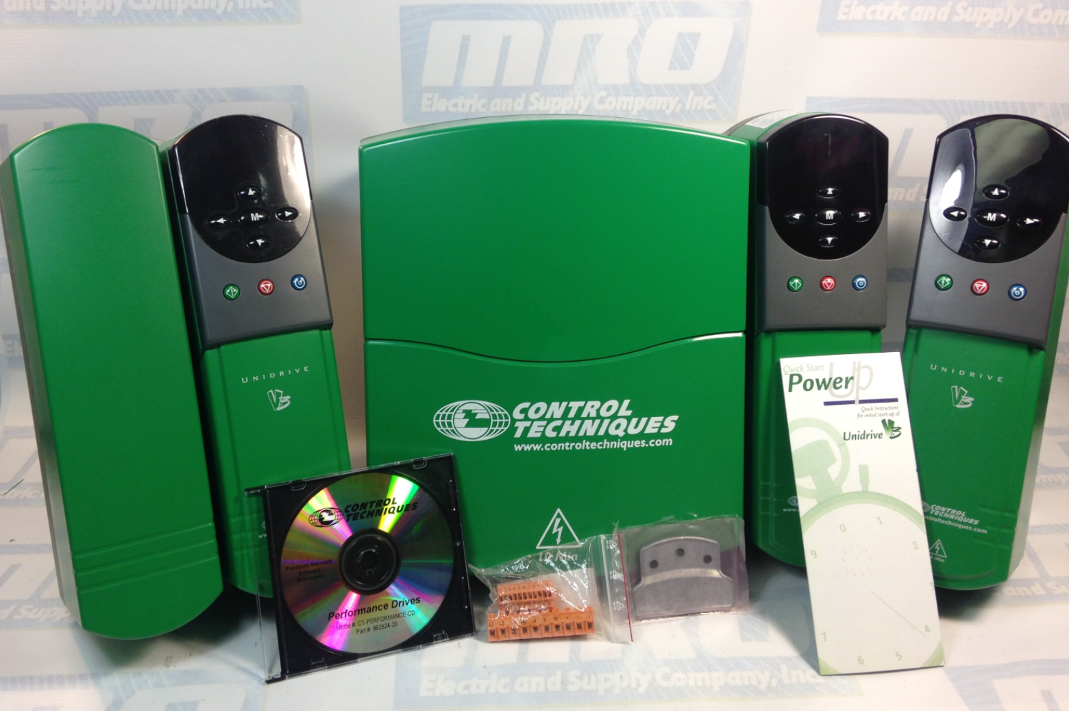
Testing a UNI3404 Drive

unidrive classic

Testing a UNI3404 Drive

Before we ship out all of our Unidrives, we fully test them to make sure everything is functioning properly. Here is an example of one of the UNI3404 Drive units that we have in stock being powered up and tested. We have all sizes of the Unidrive Classic series in stock and ready to ship if need be. Check out our repair service as well as our core exchange program.

Check out our article covering details to maintain Unidrive Classic and Unidrive SP drives here. 

MRO Electric and Supply maintains a comprehensive stock of new and used  Control Techniques Unidrive and Control Techniques Unidrive Classic SP parts. If you need a replacement part, please call 800-691-8511 or email sales@mroelectric.com.

Updated on March 5, 2020 by Brian Hughes