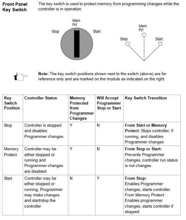
During the 140CPU53414B firmware configuration, there are two switches (a three-position slide switch and a three-position key switch) and one connector (Modbus RS-232) located on the front of the CPU.
The slide switch is used to select the comm parameter settings for the 140CPU53414B configuration of Modbus (RS-232) ports. Three options are available, ASCII, RTU, and mem.
Setting the slide switch to ASCII means the the following comm port parameters are set and cannot be changed.
– Baud: 2,400
– Parity: Even
– Data Bits: 7
– Stop Bits: 1
– Device Address: Rear panel rotary setting
Setting the switch to the RTU (remote terminal unit) setting causes the following comm parameters to be set and cannot be changed.
– Baud: 9,600
– Parity: Even
– Data Bits: 8
– Stop Bits: 1
– Device Address: Rear panel rotary switch setting
Setting the switch to the bottom mem positition gives you the ability to assign comm parameters to the port in software. The following parameters are valid.
– Baud: 50 … 19200
– Data Bits: 7/8
– Stop Bits: 1/2
– Parity: Enable/Disable and Odd/Even
– Device Address: 1 … 247
The diagram below shows the front panel of the 140CPU53414B configuration and the switch settings.

You can see our other blog post on the 140CPU53414B here. To get a 140CPU53414B price you can call 1-800-691-8511 or email sales@mroelectric.com.
Updated on March 5, 2020 by Brian Hughes
